
Flex AWD V6-3.5L (2009)
Timing Chain: Diagrams
NOTICE: The crankshaft must remain in the freewheeling position (crankshaft dowel pin at 9 o'clock) until after the camshafts are installed
and the valve clearance is checked/adjusted. Do not turn the crankshaft until instructed to do so. Failure to follow this process will result in
severe engine damage.
Position the crankshaft dowel pin in the 9 o'clock position.
NOTICE: The camshafts must remain in the neutral position during installation or engine damage may occur.
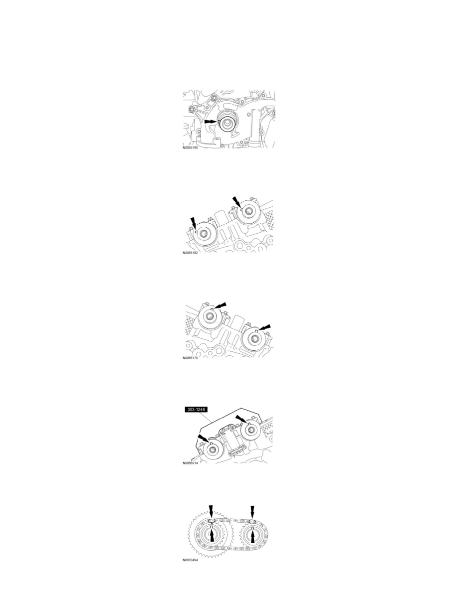
Position the camshafts onto the RH cylinder head in the neutral position as shown.
NOTICE: The camshafts must remain in the neutral position during installation or engine damage may occur.
Position the camshafts onto the LH cylinder head in the neutral position as shown.
NOTE: Use a camshaft sprocket bolt to turn the camshafts.
Rotate the RH camshafts to the Top Dead Center (TDC) position and install the Camshaft Holding Tool on the flats of the camshafts.
Assemble the RH Variable Camshaft Timing (VCT) assembly, the RH exhaust camshaft sprocket and the RH secondary timing chain.
-
Align the colored links with the timing marks.