| Removal and Installation Name Specification Silicon dielectric compound ESA-M1C171-A Removal All vehicles | | -
Remove the parking brake control boot. - Detach the boot clip.
- Remove the boot.
| | | -
NOTE:Make sure the rear brakes are at a cool temperature. Release the parking brake control to its lowest position. | | | -
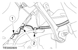
Loosen the parking brake cable adjustment nut until there is no tension in the cable. - Remove the retaining clip.
- Loosen the adjustment nut.
| | | -
Remove the wheels and tires.
For additional information, refer to: Wheel and Tire (204-04 Wheels and Tires, Removal and Installation).
| Vehicles with anti-lock brakes | | -
Detach the wheel speed sensor wiring harness from the wheel knuckle and floor panel. - Disconnect the electrical connector.
- Detach the clips.
| | | -
CAUTION:Do not remove the brake drum by means of the hub retaining nut. CAUTION:Do not damage the wheel speed sensor wiring harness or electrical connector. NOTE:The wheel speed sensor wiring harness is routed through the wheel knuckle. Remove the wheel spindle and wheel hub assembly. | Vehicles without anti-lock brakes | | -
CAUTION:Do not remove the brake drum by means of the hub retaining nut. Remove the wheel spindle and wheel hub assembly. | All vehicles | | -
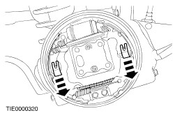
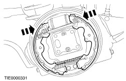
Remove the hold down springs. | | | -
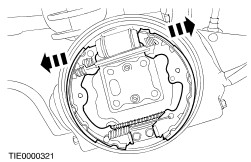
CAUTION:Do not damage the wheel cylinder boots. Disconnect the shoes from the wheel cylinder. | | | -
Detach the shoes from the anchor block. | | | -
Hold the wheel cylinder pistons in place with a rubber band. | | | -
Disconnect the parking brake cable. - Push the lever inwards.
- Disconnect the cable.
| | | -
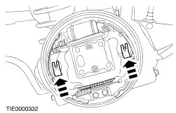
Remove the lower return spring. | | | -
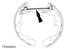
Remove the upper return spring. | | | -
Remove the primary shoe from the strut and brake shoe adjuster. - Pull the shoe outwards.
- Disconnect the strut.
- Release the strut.
| | | -
CAUTION:The strut support spring is under tension. Detach the secondary shoe from the support. - Move the strut downwards.
- Detach the parking brake return spring.
| Installation All Vehicles | | -
Install the strut support to the secondary shoe. - Install the parking brake return spring.
- Move the strut upwards.
| | | -
Install the primary shoe to the strut and brake shoe adjuster. - Install the strut.
- Push the shoe inwards.
- Rotate the adjuster fully clockwise.
| | | -
Install the upper return spring. | | | -
Install the lower return spring. | | | -
Install the parking brake cable. - Push the lever inwards.
- Connect the cable.
| | | -
Remove the rubber band holding the wheel cylinder pistons in place. | | | -
CAUTION:Do not damage the wheel cylinder boots. Connect the shoes to the wheel cylinder. | | | -
Connect the shoes to the anchor block. | | | -
Install the hold down springs. | Vehicles without anti-lock brakes | | -
CAUTION:Make sure that the mating faces are clean and free from rust and foreign material. Install the wheel spindle and wheel hub assembly. | Vehicles with anti-lock brakes | | -
CAUTION:Make sure that the mating faces are clean and free from rust and foreign material. CAUTION:Do not damage the wheel speed sensor wiring harness or electrical connector. NOTE:The wheel speed sensor wiring harness is routed through the wheel knuckle. Install the wheel spindle and wheel hub assembly. | | | -
Attach the wheel speed sensor wiring harness to the wheel knuckle and floor panel. - Connect the electrical connector.
- Attach the clips.
| All Vehicles | | -
Install the wheels and tires.
For additional information, refer to: Wheel and Tire (204-04 Wheels and Tires, Removal and Installation).
| | | -
NOTE:The internal auto adjuster must be set and the brake shoes centralized to the brake drum. Rotate the rear wheels and apply the brake pedal four times. | | | -
Adjust the parking brake cable.
For additional information, refer to: Parking Brake Cable Adjustment (206-05 Parking Brake and Actuation, General Procedures).
| |