ford Workshop Repair Guides

Ford Workshop Service and Repair Manuals

Diagnosis and Testing > < 307-05 Automatic Transmission-Transaxle External Controls - Vehicles With: 4F27E|Specifications
Automatic Transmission/Transaxle External Controls - Vehicles With: 4F27E - External Controls Focus 1999 (08/1998-12/2004)
Description and Operation

Overview

 
Item
Part Number
Description
1
-
Selector lever assembly
2
-
Selector lever
3
-
Selector lever cable
4
-
Selector lever cable grommet
5
-
Selector lever cable clip
6
-
Shift shaft lever

Selector lever cable

  • At the transaxle end the selector lever cable is attached to a ball on the lever on the shift shaft lever through the transmission range (TR) sensor.
  • The cable abutments are secured firstly to the transaxle housing and secondly to the bracket of the selector lever.
  • The adjuster for the selector lever cable is located at the transaxle side of the sheath.
  • At the selector lever end the cable is clipped onto a ball.

Selector lever cable adjuster

Adjuster in closed position; turn in the direction of the arrow to open.

Adjuster in open position; turn in the direction of the arrow to close.

  • A quick-release fastening on the selector lever cable allows adjustment of the cable relative to the conduit.
  • Adjustment is required if the transaxle or the selector lever has been removed, if the engine does not start in "P" or "N" in case of shift quality concerns or if the switch catches are incorrect.

To adjust the selector lever cable, the selector lever must be in position "D".

First open the selector lever cable adjuster.

  • To make sure the transaxle is in position "D" the cable should be removed from the shift shaft lever, the transaxle should be shifted in "D" and the selector lever cable should be clipped again onto the shift shaft lever.
  • The selector lever cable must not be stressed. The selector lever cable must be free from binding.

The selector lever cable is locked by turning the cable adjuster after making sure again the shift mechanism is in "D".

Selector Lever

Selector Lever Positions

P Park For securing the vehicle. The engine can be started. Caution: Engage only when the vehicle is stationary (the automatic transaxle will be locked. Park should be engaged when working on a vehicle when the engine is running). The selector lever can only be moved out of position ”P" if the ignition lock is at position ”II" and the foot brake pedal is depressed. In an emergency (battery discharged) the selector lever can be unlocked manually - see selector lever lock.
R Reverse Only engage when the vehicle is stationary and the engine is idling.
N Neutral The engine can be started - no power transfer to the driving wheels.
D Gears 1 to 4 (with overdrive) Position for normal driving. All four gears are shifted electronically. When the engine is stopped this mode of operation is automatically enabled. For driving with and without overdrive - see overdrive spring loaded button.
D Gears 1 to 3 (without overdrive) Position for normal driving, but without fourth gear. For driving with and without overdrive - see overdrive spring loaded button.
2 2nd gear The automatic transaxle stays in second gear.
1 1st gear The automatic transaxle stays in first gear.

Selector lever shift lock solenoid

 
Item
Part Number
Description
1
-
Solenoid
2
-
Locking pin
3
-
Manual release mechanism

Location

The selector lever shift lock solenoid is located in the selector lever bracket.

When the ignition is switched on, the selector lever shift lock solenoid is actuated by depressing the brake (signal from the stoplamp switch). This retracts the locking pin so that the selector lever can be moved out of position "P".

Function

Substitute function

  • NOTE:
    NOTE:If "P" is selected again the selector lever is locked again.
    If the brake signal should fail due to a malfunction, manual unlocking is possible.
  • The cover of the release mechanism must be removed and a suitable object (ignition key) pressed into the opening until the manual selector lever can be moved out of position "P".

Overdrive (O/D) switch

The O/D switch is located on the side of the selector lever.

The O/D switch transmits a signal to the PCM to select or suppress 4th gear in selector lever position "D".

The signal of the O/D switch is used for the following functions:

  • as an input signal to convey the drivers' wishes to the PCM.
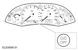
  • to display the drivers' wishes with the O/D indicator in the instrument cluster.

No substitute signal is available for the O/D switch. If it should fail, it is always possible to shift into 4th gear in selector lever position "D".

Overdrive (O/D) indicator

  • The O/D indicator is located in the instrument cluster and is coloured green.
  • The O/D indicator is actuated by the O/D switch on the selector lever. It tells the driver that shifting into 4th gear is prevented by the transaxle control.

Selector lever spring loaded button

  • To move the selector lever from park position, the ignition lock must be set to "II", the foot brake pedal must be depressed and shift release button pressed in.
  • The spring loaded side button must also be pressed, if the lever is moved from:
    -
    N and D to 2 and 1
    -
    1, 2, D and N to R and P
    -
    R to P

Powertrain warning indicator

Location

The powertrain warning indicator is located in the instrument cluster and is coloured orange.

Function

It lights to tell the driver that the transaxle control has switched to the emergency operating program or that the transmission fluid temperature is too high.

Diagnosis and Testing > < 307-05 Automatic Transmission-Transaxle External Controls - Vehicles With: 4F27E|Specifications