
Camshaft
- Make
- Ford
- Model
- Fusion Factory Service Manual
- Year
- 2007
- Section
- 303-01C Engine — 3.5L › Removal › Camshaft
Camshaft
 |
Camshaft Alignment Tool
303-1248 |
CAUTION: During engine repair procedures, cleanliness is extremely important. Any foreign material, including any material created while cleaning gasket surfaces, that enters the oil passages, coolant passages or the oil pan can cause engine failure.
All camshafts
- Remove the engine front cover. For additional information, refer to Engine Front Cover in this section.
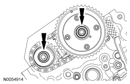
- Rotate the crankshaft clockwise and align the timing marks on the variable camshaft timing (VCT) assemblies as shown.
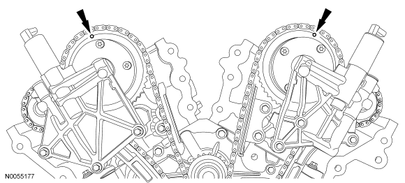
-
NOTE: The special tool will hold the camshafts in the top dead center position.
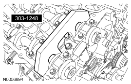
Install the special tool onto the flats of the LH camshafts.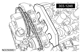
-
NOTE: The special tool will hold the camshafts in the top dead center position.
Install the special tool onto the flats of the RH camshafts.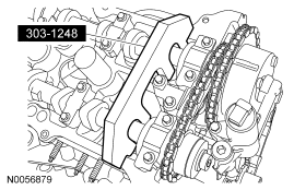
- Remove the 3 bolts and the RH VCT housing.
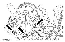
- Remove the 3 bolts and the LH VCT housing.
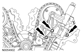
- Remove and discard the VCT housing seals.
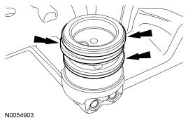
- Remove the 2 bolts and the primary timing chain tensioner.
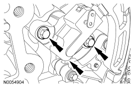
- Remove the primary timing chain tensioner arm.
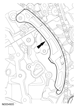
- Remove the 2 bolts and the lower LH primary timing chain guide.
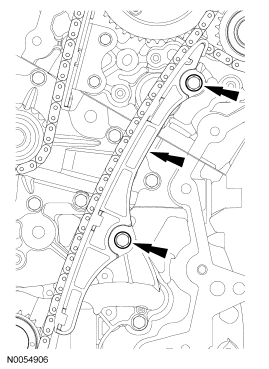
- Remove the primary timing chain.
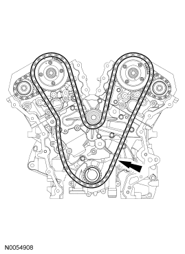
LH camshafts
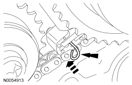
- Compress the LH secondary timing chain tensioner and install a suitable lockpin to retain the tensioner in the collapsed position.
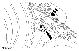
-
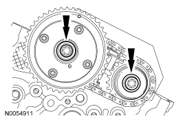
NOTE: The VCT bolt and the exhaust camshaft bolt must be discarded and new ones installed. However, the exhaust camshaft washer is reusable.
Remove and discard the LH VCT assembly bolt and the LH exhaust camshaft sprocket bolt.- Remove the LH VCT assembly, secondary timing chain and the LH exhaust camshaft sprocket as an assembly.
-
NOTE: When the special tool is removed, valve spring pressure will rotate the LH camshafts approximately 3 degrees to a neutral position.
Remove the special tool from the LH camshafts.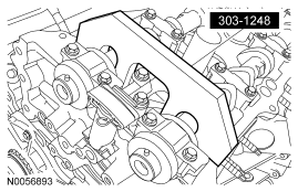
-
CAUTION: The camshafts must remain in the neutral position during removal or engine damage may occur.
Verify the LH camshafts are in the neutral position.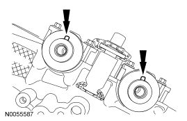
-
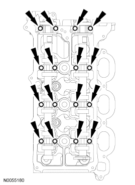
NOTE: Cylinder head camshaft bearing caps are numbered to verify that they are assembled in their original positions.
Remove the bolts and the LH camshaft bearing caps.- Remove the LH camshafts.
RH camshafts
- Compress the RH secondary timing chain tensioner and install a suitable lockpin to retain the tensioner in the collapsed position.
-
NOTE: The VCT bolt and the exhaust camshaft bolt must be discarded and new ones installed. However, the exhaust camshaft washer is reusable.
Remove and discard the RH VCT assembly bolt and the RH exhaust camshaft sprocket bolt.- Remove the RH VCT assembly, secondary timing chain and the RH exhaust camshaft sprocket as an assembly.
- Remove the special tool from the RH camshafts.
-
CAUTION: The camshafts must remain in the neutral position during removal or engine damage may occur.
Rotate the RH camshafts counterclockwise to the neutral position.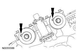
-
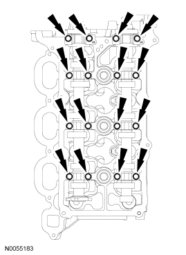
NOTE: Cylinder head camshaft bearing caps are numbered to verify that they are assembled in their original positions.
Remove the bolts and the RH camshaft bearing caps.- Remove the RH camshafts.
Parts & tools for this job For 2007 Ford Fusion
- PARTEngine gasket setSearch: Ford Fusion 2007 engine gasket set
- TOOLTorque wrenchSearch: 3/8 inch torque wrench
- TOOLFeeler gauge setSearch: feeler gauge set
Links open Amazon search results in a new tab. As an Amazon Associate I earn from qualifying purchases.