
Engine
- Make
- Ford
- Model
- Fusion Factory Service Manual
- Year
- 2007
- Section
- 303-01C Engine — 3.5L › Removal › Engine
Engine
 |
Adapter for 204-592
204-592/1 |
 |
Engine Lifting Bracket
303-1245 |
 |
Heavy Duty Floor Crane
014-00071 or equivalent |
 |
Powertrain Lift
014-00765 |
 |
Remover, Halfshaft
205-243 |
 |
Remover, Halfshaft
205-832 |
 |
Separator, Ball Joint
205-592 |
 |
Slide Hammer
100-001 |
 |
Spreader Bar
303-D089 (D93P-6001-A3) or equivalent |
 |
Tie-Rod End Remover
211-105 |
 |
Universal Adapter Brackets
014-0001 Lifting Bracket Set, Engine 303-D095 (D94L-6001-A) or equivalent |
WARNING: Do not smoke, carry lighted tobacco or have an open flame of any type when working on or near any fuel-related component. Highly flammable mixtures are always present and may be ignited. Failure to follow these instructions may result in serious personal injury.
All vehicles
- With the vehicle in NEUTRAL, position it on a hoist. For additional information, refer to Section 100-02.
- Release the fuel system pressure. For additional information, refer to Section 310-00.
- Recover the air conditioning system. For additional information, refer to Section 412-00.
- Remove the accessory drive belt and the power steering belt. For additional information, refer to Section 303-05C.
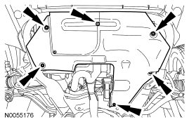
- If equipped, remove the 6 screws and the underbody shield.
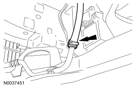
- Disconnect the power steering cooler tube and drain the power steering fluid into a suitable drain pan.
- Remove the degas bottle. For additional information, refer to Section 303-03.
- Remove the engine air cleaner and air cleaner outlet pipe. For additional information, refer to Section 303-12C.
- Remove the battery tray. For additional information, refer to Section 414-01.
- Disconnect the 2 engine wiring harness electrical connectors.
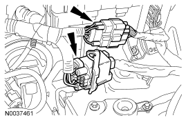
- Detach the 2 wiring harness retainers from the transmission mount and the battery tray bracket.
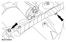
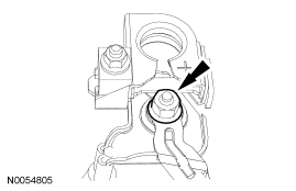
- Remove the nut and disconnect the power feed wire from the battery terminal.
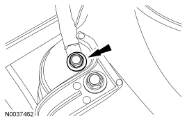
- Remove the bolt and position aside the ground wire.
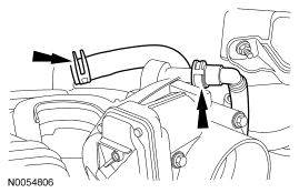
- Disconnect the vacuum hose and the evaporative emissions (EVAP) tube from the upper intake manifold.
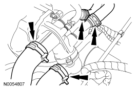
- Disconnect the upper radiator hose, lower radiator hose and 2 heater hoses from the thermostat housing.
- Disconnect the transaxle control cable from the control lever.
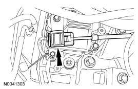
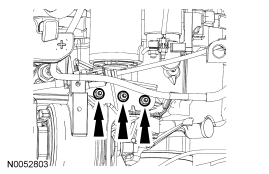
- Remove the 3 nuts and position the transaxle control cable bracket aside.
- Remove the bolt and position the ground wire aside.
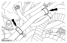
- If equipped, detach the engine block heater harness from the radiator support, power steering hose, A/C tube and the engine wiring harness.
- Detach the coolant tube retainer clips from the A/C tube.
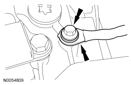
- Remove the nut and disconnect the A/C tube from the condenser.
- Discard the O-ring seal.
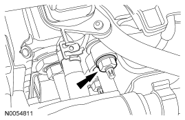
- Remove the 2 A/C tube bracket bolts.
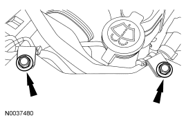
- Remove the A/C tube bracket bolt.
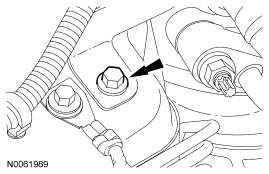
- Remove the 2 nuts and disconnect the A/C tubes.
- Discard the O-ring seal.
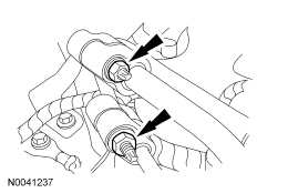
- Detach the 2 wiring harness retainers.
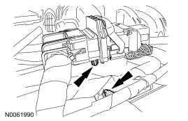
- Disconnect the 2 engine wiring harness electrical connectors.
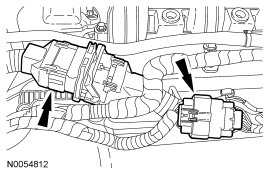
- Remove the 2 wiring harness retainers from the LH valve cover stud bolts and position the wiring harness aside.
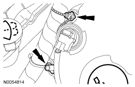
- Remove the oil level indicator.
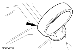
- Disconnect the hose from the power steering reservoir.
- Detach the pin-type retainer from the engine mount brace.
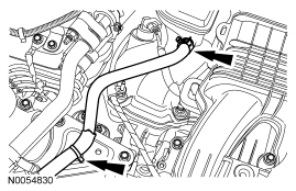
- Using a small screwdriver, release the retaining clip and detach the power steering reservoir from the cowl.
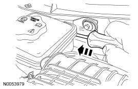
- Disconnect the fuel supply tube from the fuel rail. For additional information, refer to Section 310-00.
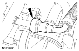
- Remove the bolt and the ground wire from the engine mount brace.
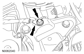
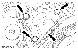
- Remove the 3 bolts and the engine mount brace.
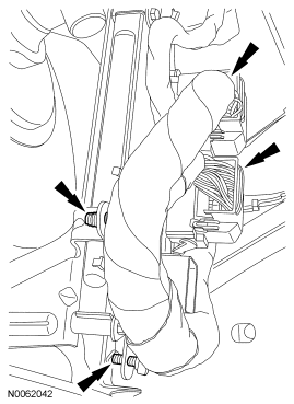
- Disconnect the PCM electrical connectors and pin-type retainers.
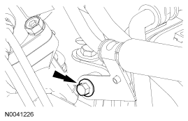
- Remove the power steering pressure (PSP) hose bracket bolt.
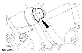
- Remove and discard the PSP hose banjo bolt and the 2 seals from the steering gear.
- Place the steering wheel in the straight-ahead position and the ignition key in the OFF position.
- Remove the 2 nuts and the steering joint cover.
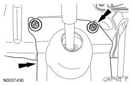
-
CAUTION: Do not allow the intermediate shaft to rotate while it is disconnected from the gear or damage to the clockspring can occur. If there is evidence that the intermediate shaft has rotated, the clockspring must be removed and recentered. For additional information, refer to Section 501-20B.
NOTE: Index the steering column shaft position to the steering gear for reference during installation.
Remove the bolt and disconnect the steering column shaft from the steering gear.- Discard the bolt.
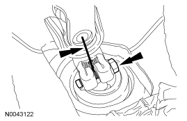
- Remove the 4 screws and position the LH fender splash shield aside.
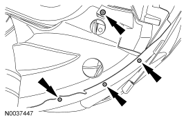
- Remove the 6 pin-type retainers (4 shown) and the LH splash shield.
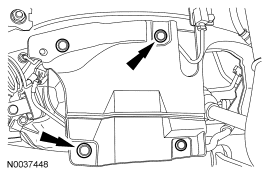
-
CAUTION: The steering gear-to-dash seal must be removed or it will be damaged when lowering the subframe.
Release the 4 clips and slide the steering gear-to-dash seal off of the steering gear and into the passenger compartment.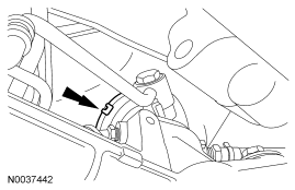
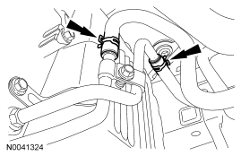
- Disconnect the transaxle cooler hoses.
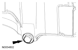
- Remove the drain plug and drain the engine oil.
- Install the drain plug and tighten to 27 Nm (20 lb-ft).
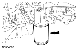
- Remove and discard the engine oil filter.
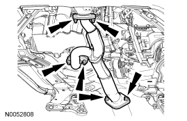
- Remove the 6 nuts and the Y-pipe assembly.
- Discard the gaskets and nuts.
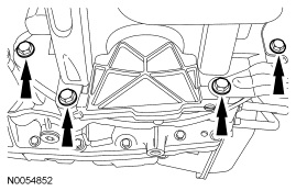
- Remove the 4 oil pan-to-transaxle bolts.
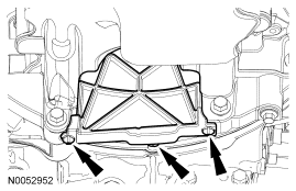
- Remove the 2 fasteners and the inspection cover.
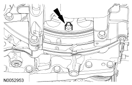
- Remove and discard the 4 torque converter nuts.
All wheel drive (AWD) vehicles
-
NOTE: Index-mark the driveshaft for installation.
Remove the 4 bolts (3 shown) and support the driveshaft with a length of mechanic's wire.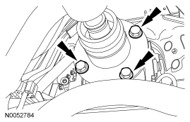
All vehicles
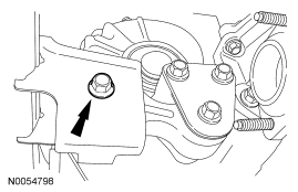
- Remove the engine roll restrictor-to-subframe through bolt.
-
NOTE: LH shown, RH similar.
Remove the cotter pins and nuts from the tie-rod ends.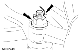
-
NOTE: LH shown, RH similar.
Using the special tool, separate the tie-rod ends from the steering knuckles.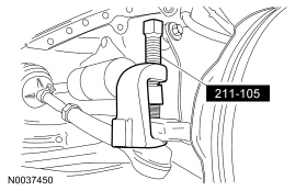
-
NOTE: LH shown, RH similar.
Remove the nuts and separate the stabilizer bar links from the struts.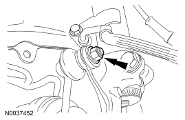
-
NOTE: LH shown, RH similar.
Remove the 4 lower ball joint nuts.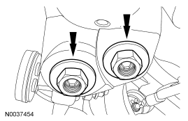
-
CAUTION: When the lower ball joint is separated from the wheel knuckle, the lower arm may strike the outer constant velocity (CV) joint boot with enough force to damage the boot clamp. This will result in a loss of grease from the outer CV joint. Place a block of wood, or similar item, between the lower arm and the outer CV joint to prevent the lower arm from striking the outer CV joint.
NOTE: Once pressure is applied to the ball joint with the special tool, it may be necessary to tap the wheel knuckle at the ball joint area to separate the ball joint from the wheel knuckle.
NOTE: LH shown, RH similar.
Using the special tools, separate the lower ball joints from the lower control arms.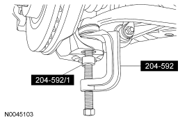
-
NOTE: LH shown, RH similar.
Remove the through bolts from the lower control arms.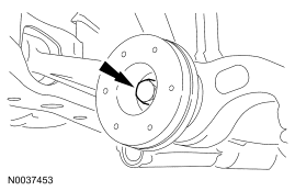
- Position the special tool under the subframe assembly.
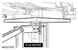
-
NOTE: LH shown, RH similar.
Remove the 4 subframe bracket-to-body bolts.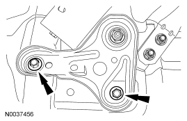
-
NOTE: LH shown, RH similar.
Remove the 2 rear subframe nuts and the 2 subframe brackets.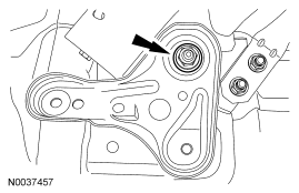
-
NOTE: LH shown, RH similar.
Remove the 2 front subframe nuts.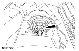
- Lower the subframe assembly from the vehicle.
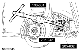
- Using the special tools, separate the LH halfshaft from the transaxle and support the halfshaft with a length of mechanic's wire.
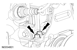
- Remove the 2 RH catalytic converter bracket bolts.
Front wheel drive (FWD) vehicles
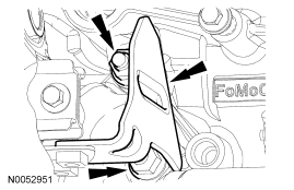
- Remove the 2 nuts and remove the RH catalytic converter bracket.
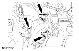
- Remove the RH halfshaft carrier bearing bolt and 2 stud bolts.
- Separate the RH halfshaft from the transaxle and support the halfshaft with a length of mechanic's wire.
AWD vehicles
- Remove the 2 RH halfshaft carrier bearing bolts.
- Separate the RH halfshaft from the transaxle and support the halfshaft with a length of mechanic's wire.
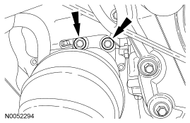
- Disconnect the RH catalyst monitor electrical connector.
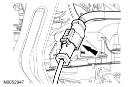
- Remove the 4 nuts and the RH catalytic converter.
- Discard the gasket.
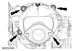
- Remove and discard the 4 RH catalytic converter-to-exhaust manifold studs.
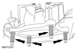
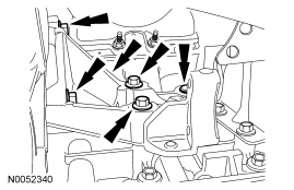
- Remove the 5 bolts and the power transfer unit (PTU) support bracket.
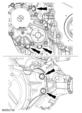
- Remove the 5 bolts and the PTU.
All vehicles
-
NOTE: Position a block of wood under the transaxle.
Install the special tools.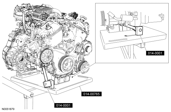
- Remove the transaxle mount through bolt and nut.
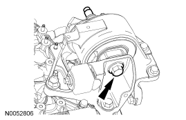
- Remove the transaxle mount bracket bolt and the 2 nuts.
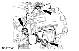
- Remove the 4 engine mount nuts.
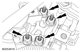
- Remove the nut, 2 bolts and the engine mount.
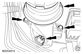
- Lower the engine and transaxle assembly from the vehicle.
- Disconnect the wiring harness fasteners from the transaxle-to-engine stud bolt and the starter.
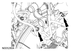
- Remove the bolt and ground wire.
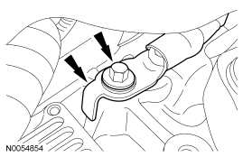
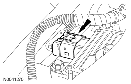
- Disconnect the transmission control module (TCM) electrical connector.
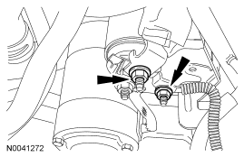
- Remove the 2 nuts and the starter motor wiring.
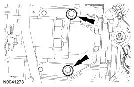
- Remove the 2 bolts and the starter.
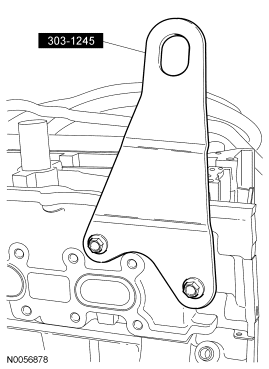
- Install the special tool on the LH cylinder head.
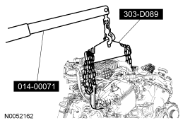
- Using the special tools and a suitable engine crane, remove the engine and transaxle from the lift table.
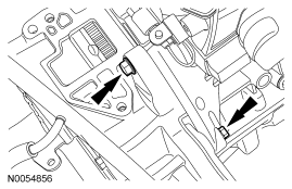
- Remove the 2 engine-to-transaxle bolts.
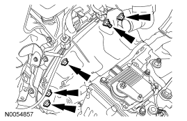
- Remove the transaxle-to-engine stud bolt and the 4 transaxle-to-engine bolts.
- Separate the transaxle from the engine.
Parts & tools for this job For 2007 Ford Fusion
- PARTEngine gasket setSearch: Ford Fusion 2007 engine gasket set
- TOOLTorque wrenchSearch: 3/8 inch torque wrench
- TOOLFeeler gauge setSearch: feeler gauge set
Links open Amazon search results in a new tab. As an Amazon Associate I earn from qualifying purchases.