| Assembly Special Tool(s) | | Flange Holding Wrench, Universal 205-072 (15-030A) | | | Angle Gauge, Bolt Tightening 303-174 (21-540) | | | Locking Tool, Flywheel 303-254 (21-135) | | | Installer, Crankshaft Rear Oil Seal 303-291 (21-141) | | | Socket, Cylinder Head Bolt 303-392 (21-167) | | | Remover/Installer, Hose 303-397 (24-003) | | | Mounting Stand 303-435 (21-187) | | | Mounting Bracket for 303-435 303-435-04 (21-064) | | | Mounting Plate for 303-435 303-435-12 (21-150A) | | | Remover, Vibration Damper Hub 303-509 (21-213) | | | Installer, Crankshaft Vibration Damper 303-510 (21-214) | General Equipment Oil filter strap wrench Piston ring compressor Straight edge Feeler gauge set One M6 x 60 mm bolt Two M8 x 30 mm bolts Three M8 x 25 mm bolts Materials Name Specification Engine oil WSS-M2C913-A or WSS-M2C912-A1 Silicon grease A960-M1C171-AA Lubricant WSD-M1C226-A Sealer (Loctite 243) WSE-M4G323-A6 Sealer WSK-M2G348-05 or ESK-M4G269-A Loctite 7070 Welding rod Assembly | | -
Clean the mating faces of the cylinder head and the cylinder block with Loctite 7070. | | | -
NOTE:Coat the crankshaft thrust half-washers with clean engine oil. NOTE:The grooves in the crankshaft thrust half-washers must face outwards. Install the crankshaft thrust half-washers. | | | -
NOTE:Coat the crankshaft and the crankshaft bearing shells with clean engine oil. Install the crankshaft. | | | -
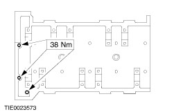
NOTE:Coat the crankshaft bearing shells with clean engine oil. NOTE:Do not fully tighten the retaining bolts and studs at this stage. Install the crankshaft main bearing caps. - Install the bolts.
- Install the studs.
| | | -
Tighten the retaining bolts and studs. | | | -
NOTE:The piston ring gaps must be distributed evenly around the circumference of the piston. This also applies to the oil control ring elements. Align the piston ring gaps at 120 degrees to each other. | | | -
Coat the connecting rod bearing shells with clean engine oil. | | | -
Install the connecting rod bearing caps. - Tighten the bolts in three stages.
- Stage 1: 3 Nm.
- Stage 2: 16 Nm.
- Stage 3: 90 degrees.
| | | -
NOTE:Install a new crankshaft rear oil seal carrier gasket. NOTE:Do not fully tighten the crankshaft rear oil seal carrier retaining bolts at this stage. Install the crankshaft rear oil seal carrier. | | | -
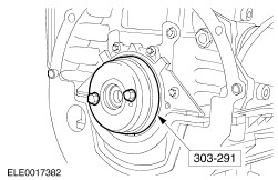
NOTE:Install a new crankshaft rear oil seal. Using the special tool and two old flywheel bolts, install the crankshaft rear oil seal. | | | -
Align the crankshaft rear oil seal carrier with the cylinder block so that there is a step not exceeding 0.46 mm on each side and tighten the retaining bolts. | | | -
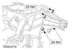
Apply two beads of sealer, 3 mm diameter and 10 mm length. | | | -
NOTE:Do not remove displaced sealer. Install the front arch. | | | -
NOTE:Install a new oil pick-up tube gasket. Install the oil pick-up tube. | | | -
Apply sealer to the mating faces of the cylinder block and the crankshaft rear oil sealer carrier (as shown). | | | -
NOTE:Install a new oil pan gasket. NOTE:Do not fully tighten the bolts and nuts at this stage. Install the oil pan. | | | -
NOTE:The gap between the cylinder block and the oil pan must be eliminated using adjusting shims when installing the transmission. | | | -
Tighten the oil pan retaining bolts and nut. | | | -
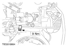
Install the crankshaft position (CKP) sensor. | | | -
Install the oil pressure switch. | | | -
NOTE:Install a new oil pump gasket. Install the oil pump. | | | -
NOTE:Install a new water pump O-ring seal. Install the water pump. | | | -
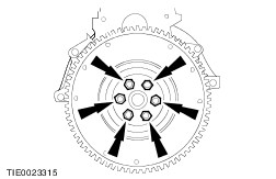
NOTE:Install new flywheel bolts. NOTE:Do not fully tighten the flywheel bolts at this stage. Install the flywheel. | | | -
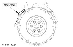
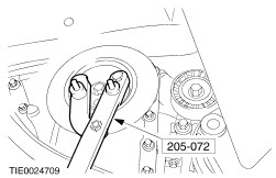
Using the special tool, lock the flywheel in position. | | | -
Tighten the flywheel bolts. | | | -
Install the clutch disc and pressure plate. For additional information, refer to Section 308-01 Clutch. | | | -
CAUTION:Do not reuse the cylinder head bolts if the length is more than 174.3 mm. Measure the cylinder head bolts. | | | -
CAUTION:Do not install the front three cylinder heads bolts at this stage. CAUTION:Install new cylinder head bolts as necessary. NOTE:Install a new cylinder head gasket. Using the special tool, install the cylinder head. - Tighten the bolts in the sequence shown in four stages.
- Stage 1: Tighten bolts 1 through 10 to 10 Nm.
- Stage 2: Tighten bolts 1 through 10 to 35 Nm.
- Stage 3: Tighten bolts 1 through 10 to 90 degrees.
- Stage 4: Tighten bolts 1 through 10 to 90 degrees.
| | | -
Install the front three cylinder head bolts. | | | -
NOTE:Only turn the crankshaft in the normal direction of rotation. Turn the crankshaft to 45 degrees after TDC. | | | -
Coat the camshaft and the camshaft bearing shells with clean engine oil. | | | -
NOTE:The intake camshaft is marked with an R and the exhaust camshaft marked with L. Install the camshafts so that none of the cams are at full lift. | | | -
CAUTION:The camshaft must not be turned for at least 15 minutes after tightening the camshaft bearing cap retaining bolts. NOTE:The installation location of the camshaft bearing caps are marked on the rear face of the caps. Install the camshaft bearing caps and the timing chain upper guide bracket. | | | -
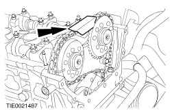
NOTE:Only turn the crankshaft in the normal direction of rotation. Turn the crankshaft to TDC and position the camshafts as shown. | | | -
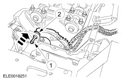
CAUTION:The copper link of the timing chain must align with the timing mark on the crankshaft sprocket. Install the timing chain and the timing chain lower guide. - Guide the timing chain through the cylinder head and secure it to the cylinder head to prevent it from dropping into the timing case.
| | | -
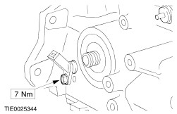
Tighten the timing chain lower guide retaining bolt. | | | -
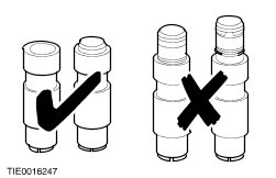
CAUTION:Do not install a fully or partially released timing chain tensioner. Install a new timing chain tensioner. | | | -
CAUTION:Prevent the timing chain tensioner retaining washer from dropping into the timing case. Install the timing chain tensioner arm. - Using a M6 x 60 mm bolt, install the timing chain tensioner pivot bolt.
- Install the retaining washer.
| | | -
Install the timing chain right-hand guide upper retaining bolt. | | | -
CAUTION:Make sure that the camshaft sprocket correctly locate into the slots on the camshaft. CAUTION:The copper link of the timing chain must align with the timing mark on the camshaft sprocket. NOTE:Do not fully tighten the camshaft sprocket retaining bolt at this stage. Install the exhaust camshaft sprocket and the timing chain. | | | -
CAUTION:Make sure that the camshaft sprocket correctly locates into the slots on the camshaft. CAUTION:The copper links of the timing chain must align with the timing mark on the camshaft sprockets. NOTE:Do not fully tighten the camshaft sprocket retaining bolt at this stage. Install the intake camshaft sprocket and the timing chain. | | | -
NOTE:Install a new timing chain upper guide. Install the timing chain upper guide. | | | -
NOTE:If the plunger of the timing chain tensioner does not reach the timing chain tensioner, use the special tool to release it as described in the following two steps. Using a suitable brass drift, release the timing chain tensioner. | | | -
Using a 220 mm length of suitable 2.5 mm diameter welding rod, fabricate a special tool. | | | -
Release the timing chain tensioner. - Press the timing chain tensioner arm down by hand and release the timing chain tensioner.
| | | -
Using the special tool, tighten the camshaft sprocket retaining bolts. | | | -
NOTE:Only turn the crankshaft in the normal direction of rotation. Turn the crankshaft two revolutions. | | | -
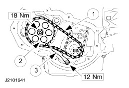
Install the oil pump chain. - Install the oil pump chain guides.
- Install the oil pump sprocket and the oil pump drive chain.
- Install the oil pump tensioner.
| | | -
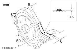
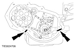
Apply two beads of sealer 3-5 mm in diameter and 10 mm long at two places as shown. | | | -
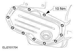
NOTE:Install a new engine front cover. NOTE:A new engine front cover is supplied with a crankshaft front oil alignment sleeve that must be removed following installation. Install the engine front cover. | | | -
Remove the crankshaft front oil seal alignment sleeve. | | | -
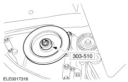
Using the special tool, install the crankshaft pulley. | | | -
Remove the special tool from the crankshaft pulley. | | | -
NOTE:Do not fully tighten the crankshaft pulley retaining bolt at this stage. Install a new crankshaft pulley retaining bolt. | | | -
Tighten the crankshaft pulley retaining bolt in two stages. | | | -
Remove the special tools from the crankshaft pulley. | | | -
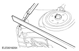
NOTE:Install a new engine upper front cover gasket. Install the engine upper front cover. - Use a suitable straight edge to align the top edge of the engine upper front cover with the cylinder head.
| | | -
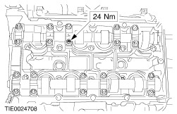
NOTE:Install a new valve cover gasket. Install the valve cover. - Tighten the nuts and bolts in the sequence shown in two stages.
- Stage 1: Tighten nuts and bolts 1 through 15 to 3 Nm.
- Stage 2: Tighten nuts and bolts 1 through 15 to 9 Nm.
| | | -
Install the engine support plate. | | | -
Install the water pump pulley. | | | -
Install the engine front lifting eye and the engine support plate bracket. | | | -
NOTE:Install new intake manifold gaskets. Install the intake manifold. | | | -
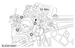
NOTE:Install a new throttle body O-ring seal. Install the throttle body. | | | -
NOTE:Install a new IAC gasket. Install the idle air control (IAC) valve. | | | -
Attach the throttle body bracket to the throttle body. | | | -
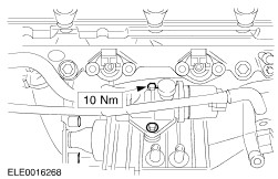
NOTE:Install a new coolant outlet housing gasket. Install the coolant outlet housing. | | | -
Install the positive crankcase ventilation (PCV) tube. | | | -
NOTE:Install new exhaust manifold retaining nuts and a new exhaust manifold gasket. Install the exhaust manifold. | | | -
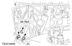
NOTE:Pull back the accessory drive belt tensioner. Install the power steering pump and generator bracket. | | | -
Install the oil level indicator and tube. | | | -
Install the exhaust manifold heat shield. | | | -
Using the special tool, connect the coolant hose to the water pump. | | | -
Install the engine support plate bracket and the generator bracket to the cylinder head. | | | -
NOTE:Use a suitable blunt object to avoid damage to the spark plug connector gasket. Coat the inside of the spark plug connector with silicone grease to a depth of 5-10 mm. | | | -
Connect the spark plug electrical connectors. | | | -
Connect the power supply rail to the fuel injectors. | | | -
Install the engine rear lifting eye. | | | -
Install the ignition coil and spark plug wires. | | | -
Connect the IAC valve electrical connector. | | | -
Connect the throttle position (TP) sensor electrical connector. | | | -
Attach the generator wiring harness support guide to the cylinder head. | | | -
Connect the camshaft position (CMP) sensor electrical connector. | | | -
Connect the ignition coil electrical connectors. | | | -
Connect the engine cooling fan temperature switch and engine coolant temperature sender unit electrical connectors. | | | -
Using a suitable engine hoist, remove the engine from the mounting stand. | | | -
Connect the crankshaft position (CKP) sensor electrical connectors. | | | -
Connect the oil pressure switch electrical connector. | | | -
Using a suitable oil filter strap wrench, install a new oil filter. | | | -
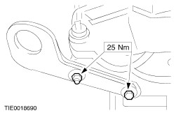
Install the halfshaft center bearing bracket. | | |