| Installation Special Tool(s) | | Angle Gauge, Bolt Tightening 303-174 (21-540) | | | Remover/Installer, Hose Clamp 303-397 (24-003) | General Equipment Transmission jack Workshop table Engine hoist Securing straps Materials Name Specification Locking compound SDM-4G9107-A Installation | | -
WARNING:Do not smoke or carry lighted tobacco or open flame of any type when working on or near any fuel related components. Highly flammable mixtures are always present and may ignite. Failure to follow these instructions may result in personal injury. Align the adapter plate to the engine and transaxle. | | | -
CAUTION:Make sure that the two locating tubes are installed. NOTE:Make sure that the intermediate shaft remains in the transaxle. Install the transaxle. - Install the transaxle left-hand retaining bolts.
| | | -
Install the transaxle lower and right-hand retaining bolts. | | | -
Connect the vehicle speed sensor (VSS) and the heated oxygen sensor (HO2S) electrical connectors. | | | -
Connect the starter motor solenoid electrical connector. | | | -
WARNING:Support the engine and transaxle assembly on wooden blocks and secure it with suitable securing straps (engine shown removed for clarity). Position the engine and transaxle assembly in the engine compartment. | | | -
NOTE:Do not tighten the engine rear mount retaining bolts and nut at this stage. Install the engine rear mount. - Install the bolt.
- Install new bolts and a new nut.
| | | -
NOTE:Do not tighten the engine front mount retaining bolts and nut at this stage. Install the engine front mount. - Install the bolts.
- Install the nut.
| | | -
Remove the securing straps. | | | -
Install the engine support insulator. - Tighten the bolt.
- Tighten the bolt in two stages.
| | | -
Tighten the engine front mount retaining bolts and nuts. - Tighten the bolts.
- Tighten the nut.
- Connect the engine ground cable to the bolt.
| | | -
Tighten the engine rear mount retaining nut and bolts. - Tighten the bolt.
- Tighten the bolts and nut in two stages.
- Tighten the bolts in two stages.
| | | -
Attach the air conditioning (A/C) compressor to the engine. - Install the retaining bolts.
- Install the refrigerant line support bracket.
- Install the heat shield.
| | | -
CAUTION:Secure the halfshaft to prevent damage to the CV joints. The inner CV joint must not be bent more than 20 degrees. The outer CV joint must not be bent more than 50 degrees. CAUTION:Do not damage the halfshaft seal. NOTE:Make sure that the snap ring is correctly seated. Attach the left-hand halfshaft to the transaxle. - Allow the oil to drain into a suitable container.
| | | -
CAUTION:Secure the halfshaft to prevent damage to the CV joints. The inner CV joint must not be bent more than 20 degrees. The outer CV joint must not be bent more than 50 degrees. CAUTION:Do not damage the halfshaft seal. NOTE:Install a new intermediate shaft center bearing cap and locknuts. Attach the halfshaft together with the intermediate shaft to the transaxle. | | | -
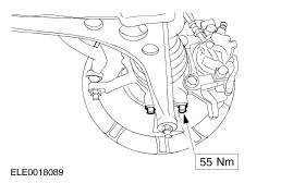
Attach the lower arms to the wheel knuckles (left-hand side shown). | | | -
WARNING:Install new tie-rod end retaining nut. Failure to follow this instruction may result in personal injury. Attach theleft-hand tie-rod end to the wheel knuckle. - Tighten the nut in two stages.
| | | -
Attach the power steering pump to the engine. - Attach the power steering line retaining bracket to the cylinder block.
| | | -
Connect the A/C compressor clutch electrical connector. | | | -
Attach the power steering line retaining bracket to the cylinder block. | | | -
Using a 9 mm Allen key to prevent the power steering pump pulley from rotation, install the power steering pump pulley. | | | -
Attach the generator positive cable to the starter motor bracket and to the side member. | | | -
Connect the starter motor ground cable. | | | -
Connect the heated oxygen sensor (HO2S) electrical connector. - Attach the HO2S cable to the transaxle.
| | | -
Connect the generator electrical connectors. | | | -
Install the radiator grille opening panel. | | | -
Install the radiator grille opening panel lower retaining bolts (right-hand side shown). - Install the radiator grille opening panel lower retaining bolts.
- Remove the two M10 x 250 mm guide bars and install the radiator grille opening panel upper retaining bolts.
| | | -
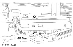
Attach the radiator grille opening panel reinforcement to the fender apron panels (left-hand side shown). | | | -
Install the front bumper cover. For additional information, refer to Section 501-19 Bumpers. | | | -
Connect the fuel supply and return line quick release coupling. For additional information, refer to Section 310-01 Fuel Tank and Lines. | | | -
Connect the battery positive cable to the battery junction box. | | | -
Attach the coolant pipe to the transaxle. | | | -
Using the special tool, connect the coolant hoses to the coolant pipes. | | | -
Using the special tool, connect the coolant hoses to the coolant outlet housing. | | | -
NOTE:Make sure the spring clip is correctly installed. Connect the clutch slave cylinder supply line to the transaxle and install the spring clip. | | | -
Attach the clutch slave cylinder supply line to the gearshift cable bracket. | | | -
Attach the gearshift cables to the transaxle. | | | -
Connect the vacuum hoses to the intake manifold. - Connect the brake booster vacuum hose.
- Connect the vacuum hoses.
| | | -
Connect the accelerator cable to the throttle body. | | | -
Attach the accelerator cable bracket to the throttle body. | | | -
Install the battery tray. - Attach the wiring harness rail to the battery tray.
- Attach the coolant hose to the battery tray.
| | | -
Install the battery side cover. - Attach the cooling system degas hose to the battery side cover.
- Attach the engine wiring harness electrical connector to the retaining bracket.
| | | -
Connect the engine wiring harness electrical connectors. - Connect the engine wiring harness electrical connector.
- Connect the engine coolant level sensor electrical connector.
| | | -
Connect the battery positive cable to the battery terminal clamp. | | | -
Using the special tool, connect the coolant hose to the coolant distribution tube. | | | -
Install the engine undershield. | | |