| Installation Special Tool(s) | | Flange Holding Wrench, Universal 205-072 (15-030A) | | | Remover/Installer, Cooling Hose Clamp 303-397 (24-003) | | | Splined Bit Set (M12/M14) 303-702 (21-253) | General Equipment Engine hoist Workshop table 5 mm drill bit Steel straight edge Installation WARNING:Do not smoke or carry lighted tobacco or open flame of any type when working on or near any fuel related components. Highly flammable mixtures are always present and may ignite. Failure to follow these instructions may result in personal injury. Vehicles with automatic transaxle | | -
CAUTION:The torque converter hub must engage fully in the oil pump drive gear. Check the installation depth of the torque converter. - Using a suitable steel straight edge, check the installation depth between the transaxle flange and the drive plate studs.
| All vehicles | | -
CAUTION:Make sure that the two locating dowels are installed. Install the transaxle to the engine. | Vehicles with manual transaxle | | -
Install the transaxle upper retaining bolts. | | | -
Install the transaxle left-hand retaining bolts. | | | -
Install the transaxle right-hand retaining bolts and the center bearing carrier. - Install the transaxle right-hand retaining bolts.
- Install the center bearing carrier (four bolts).
| | | -
Install the center bearing carrier bracket to the cylinder block. | | | -
Connect the vehicle speed (VSS) sensor electrical connector. | | | -
Connect the starter motor electrical connectors. | Vehicles with automatic transaxle | | -
NOTE:Length of the bolts. NOTE:Do not fully tighten the transaxle retaining bolts at this stage. Install the transaxle retaining bolts. - M12 x 40 mm
- M12 x 60 mm
- M12 x 70 mm
- M12 x 55 mm
| | | -
Using the special tool, tighten the transaxle left-hand retaining bolts (two bolts). | | | -
Using the special tool, tighten the transaxle lower retaining bolts. | | | -
NOTE:Install new torque converter retaining nuts. Install the torque converter to the engine drive plate (three nuts) and install the torque converter plastic cover. - Rotate the torque converter to gain access to remaining nuts.
| | | -
Using the special tool, tighten the transaxle right-hand retaining bolt. | | | -
Install the secondary air injection (AIR) pump. - Attach the hose.
- Connect the electrical connector.
- Install the bolts.
| | | -
Attach the center bearing to the center bearing carrier. | | | -
Tighten the transaxle upper retaining bolts. | All vehicles | | -
Position the workshop table with the engine and transaxle assembly underneath the vehicle and carefully lower the vehicle. | | | -
NOTE:Do not tighten the nut and bolts at this stage. Install the engine front mounting bracket. - Connect the ground cable to the engine front mounting bracket.
- Install the nuts and bolts.
| | | -
NOTE:Do not tighten the nut and bolts at this stage. Install the engine and transaxle rear mounting. | Vehicles with automatic transaxle | | -
CAUTION:Support the halfshaft. The inner joint must not be bent more than 20 degrees. The outer joint must not be bent more than 50 degrees. Attach the left-hand halfshaft to the transaxle. | | | -
CAUTION:Support the halfshaft. The inner joint must not be bent more than 18 degrees. The outer joint must not be bent more than 45 degrees. NOTE:Install a new constant velocity (CV) joint boot clamp. Attach the right-hand halfshaft to the tripode housing. | | | -
Attach the right-hand lower arm to the wheel knuckle. | | | -
Install the engine support insulator retaining bolt. | | | -
Attach the air conditioning compressor (A/C) to the engine. | | | -
Attach the A/C line support bracket to the cylinder block. | | | -
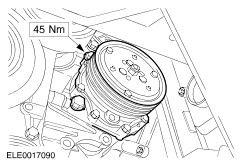
Using the special tool, install the power steering pump pulley. | Vehicles with manual transaxle | | -
CAUTION:Support the halfshaft. The inner joint must not be bent more than 20 degrees. The outer joint must not be bent more than 50 degrees. Attach the right-hand halfshaft to the center bearing carrier. | | | -
Attach the power steering pump to the engine. | All vehicles | | -
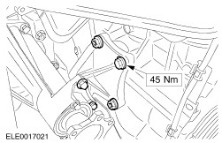
Tighten the engine front mounting retaining bolts. - Install the nuts and bolts.
- Tighten the ground cable retaining nut.
| | | -
Tighten the engine and transaxle rear mounting nut and bolts. - Tighten the engine and transaxle rear mounting bolts in the sequence shown.
- Tighten the bolt.
- Tighten the bolts in two stages.
- Tighten the bolts in two stages.
| Vehicles with manual transaxle | | -
Connect the reversing lamp switch electrical connector. | | | -
Connect the clutch slave cylinder supply line to the transaxle. - Connect the quick-release connector.
- Install the spring clip.
| | | -
Attach the clutch slave cylinder supply line to the selector cable bracket. | All vehicles | | -
Attach the power steering high pressure line retaining bracket. | | | -
NOTE:Install new exhaust flange gaskets. Connect the exhaust downpipe to the exhaust manifold (six nuts). | | | -
NOTE:Install a new exhaust flange gasket. Connect the exhaust pipe to the exhaust downpipe (three bolts). | | | -
Slide the radiator grille opening panel reinforcement backwards. | | | -
Attach the radiator grille opening panel reinforcement to the front bumper mounting brackets. - Install the front bumper lower retaining bolts.
- Remove the two M10 x 250 mm threaded bars and install the front bumper upper retaining bolts.
| | | -
Attach the radiator grille opening panel reinforcement to the fender on both sides. | | | -
Install the front bumper cover. For additional information, refer to Section 501-19 Bumpers. | | | -
NOTE:Note the fuel lines color coding. | | | -
Connect the evaporative emission solenoid valve hose. | | | -
Connect the brake booster vacuum line and the fuel pressure regulator vacuum line to the intake manifold. | Vehicles with manual transaxle | | -
Attach the gearshift and selector cables to the transaxle. - Release the locking mechanism clockwise to unlock.
- Install the cables, turning the abutment collar counterclockwise.
| | | -
Release the gearshift mechanism. | | | -
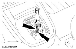
Install the gearshift lever boot and knob. | Vehicles with automatic transaxle | | -
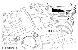
Using the special tool, connect the coolant hose to the transaxle oil cooler. | | | -
Connect the transaxle control electrical connector. | | | -
Connect the transmission range (TR) sensor electrical connector. | | | -
Install the selector lever cable to the transaxle. - Attach the selector cable.
- Install the selector cable bracket to the transaxle.
| | | -
Attach the selector lever cable to the bracket. | | | -
Connect the starter motor. - Connect the electrical connector.
- Attach the battery cable to the starter motor.
- Install the protective cap.
| All vehicles | | -
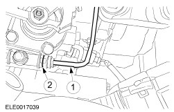
Using the special tool, connect the coolant hoses to the cylinder head and the throttle body. | | | -
Using the special tool, connect the coolant hoses to the thermostat housing. | | | -
Connect the generator positive cable to the battery junction box. | | | -
Using the special tool, connect the coolant hoses to the coolant expansion tank. | | | -
Install the battery tray. | | | -
Install the battery side cover. | | | -
Connect the powertrain control module (PCM) electrical connector. | | | -
Connect the engine wiring harness electrical connectors. - Attach the wiring harness to the battery tray
| | | -
Connect the engine coolant level indicator electrical connector. | Vehicles with manual transaxle All vehicles | | -
Check the engine oil level and correct as necessary. | | | -
Install the bulkhead cover. | | | -
Install the engine upper cover. | |