| PINPOINT TEST B : ONE OR MORE PARKING, REAR OR LICENSE LAMP IS INOPERATIVE (WITH PARK LIGHT ON) |
| TEST CONDITIONS | DETAILS/RESULTS/ACTIONS |
| B1: DETERMINE THE FAULT CONDITION |
| | 1 Turn on the PARK LIGHT. |
| | 2 Check the parking lamps. |
| | Are all parking and rear lamps inoperative? Yes No Parking and rear lamps, left-hand side are inoperative: GO to B3. Parking and rear lamps, right-hand side are inoperative: GO to B6. Front parking lamp, left-hand side is inoperative: vehicles with conventional headlamps: GO to B9. Front parking lamp, left-hand side is inoperative: vehicles with xenon headlamps: GO to B11. Front parking lamp, right-hand side is inoperative: vehicles with conventional headlamps: GO to B13. Front parking lamp, right-hand side is inoperative: vehicles with xenon headlamps: GO to B15. Rear lamp left-hand side is inoperative: GO to B17. Rear lamp right-hand side is inoperative: GO to B19. License lamp(s) is/are inoperative: GO to B21. |
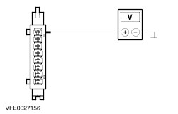
| B2: CHECK THE VOLTAGE AT THE LIGHT SWITCH |
| | 1 Ignition switch in position 0. |
| | 2 Disconnect Light switch C168. |
| | 3 Measure the voltage between light switch, connector C168, pin 15, circuit (RD/YE), harness side and ground. |
| | Is battery voltage indicated? Yes CHECK the light switch according to the Component Test attached to procedure Headlamps, if necessary INSTALL a new one. TEST the system for normal operation. No REPAIR the open circuit (RD/YE), between light switch and splice S10, by using the wiring diagrams. TEST the system for normal operation. |
| B3: CHECK FUSE F57 (CJB) |
| | 1 Ignition switch in position 0. |
| | 2 CHECK Fuse F57 (CJB). |
| | 3 Check fuse F57 (5 A). |
| | Is the fuse OK? Yes No INSTALL a new fuse F57 (5 A) and TEST the system for normal operation. If the fuse blows again, LOCATE and REPAIR the short circuit by using the wiring diagrams. TEST the system for normal operation. |
| B4: CHECK THE VOLTAGE AT FUSE F57 (CJB) |
| | 1 Connect Fuse F57 (CJB). |
| | 2 Turn on the PARK LIGHT. |
| | 3 Measure the voltage between fuse F57 (5 A) and ground. |
| | Is battery voltage indicated? Yes CHECK the CJB, if necessary INSTALL a new one. TEST the system for normal operation. No |
| B5: CHECK THE CIRCUIT BETWEEN LIGHT SWITCH AND FUSE F57 (CJB) FOR OPEN |
| | 1 Disconnect Light switch C168. |
| | 2 Measure the resistance between light switch, connector C168, pin 13, circuit (GY/BK), harness side and fuse F57 (CJB). |
| | Is the resistance less than 2 ohms? Yes CHECK the light switch according to the Component Test attached to procedure Headlamps, if necessary INSTALL a new one. TEST the system for normal operation. No LOCATE and REPAIR the open, in circuit between light switch and fuse F57 (CJB), by using the wiring diagrams. If necessary INSTALL a new CJB. TEST the system for normal operation. |
| B6: CHECK FUSE F56 (CJB) |
| | 1 Ignition switch in position 0. |
| | 2 CHECK Fuse F56 (CJB). |
| | 3 Check fuse F56 (5 A). |
| | Is the fuse OK? Yes No INSTALL a new fuse F56 (5 A) and TEST the system for normal operation. If the fuse blows again, LOCATE and REPAIR the short circuit by using the wiring diagrams. TEST the system for normal operation. |
| B7: CHECK THE VOLTAGE AT FUSE F56 |
| | 1 Connect Fuse F56 (CJB). |
| | 2 Turn on the PARK LIGHT. |
| | 3 Measure the voltage between fuse F56 (5 A) and ground. |
| | Is battery voltage indicated? Yes CHECK the CJB, if necessary INSTALL a new one. TEST the system for normal operation. No |
| B8: CHECK THE CIRCUIT BETWEEN LIGHT SWITCH AND FUSE F56 (CJB) FOR OPEN |
| | 1 Disconnect Light switch C168. |
| | 2 Measure the resistance between light switch, connector C168, pin 14, circuit (GY/RD), harness side and fuse F56 (CJB). |
| | Is the resistance less than 2 ohms? Yes CHECK the light switch according to the Component Test attached to procedure Headlamps, if necessary INSTALL a new one. TEST the system for normal operation. No LOCATE and REPAIR the open, in circuit between light switch and fuse F56 (CJB), by using the wiring diagrams. If necessary INSTALL a new CJB. TEST the system for normal operation. |
| B9: CHECK THE VOLTAGE AT THE HEADLAMP LEFT-HAND SIDE |
| | 1 Disconnect Headlamp left-hand side C194. |
| | 2 Measure the voltage between headlamp left-hand side, connector C194, pin 10, circuit (GY/BK), harness side and ground. |
| | Is battery voltage indicated? Yes No LOCATE and REPAIR the open, in circuit between fuse F57 (CJB) and headlamp, by using the wiring diagrams. If necessary INSTALL a new CJB. TEST the system for normal operation. |
| B10: CHECK THE GROUND CONNECTION OF THE HEADLAMP LEFT-HAND SIDE |
| | 1 Measure the resistance between headlamp left-hand side, connector C194, pin 4, circuit (BN), harness side and ground. |
| | Is the resistance less than 2 ohms? Yes CHECK the headlamp, if necessary INSTALL a new one. TEST the system for normal operation. No REPAIR the open circuit (BN), between headlamp left-hand side and ground G3, by using the wiring diagrams. TEST the system for normal operation. |
| B11: CHECK THE VOLTAGE AT THE XENON HEADLAMP LEFT-HAND SIDE |
| | 1 Ignition switch in position 0. |
| | 2 Disconnect Headlamp left-hand side C271. |
| | 3 Turn on the PARK LIGHT. |
| | 4 Measure the voltage between headlamp left-hand side, connector C271, pin 4, circuit (GY/BK), harness side and ground. |
| | Is battery voltage indicated? Yes No LOCATE and REPAIR the open, in circuit between fuse F57 (CJB) and headlamp, by using the wiring diagrams. If necessary INSTALL a new CJB. TEST the system for normal operation. |
| B12: CHECK THE GROUND CONNECTION OF THE XENON HEADLAMP LEFT-HAND SIDE |
| | 1 Measure the resistance between headlamp left-hand side, connector C271, pin 7, circuit (BN), harness side and ground. |
| | Is the resistance less than 2 ohms? Yes CHECK the headlamp, if necessary INSTALL a new one (master-headlamp). TEST the system for normal operation. No REPAIR the open circuit (BN), between headlamp left-hand side and ground G3, by using the wiring diagrams. TEST the system for normal operation. |
| B13: CHECK THE VOLTAGE AT THE HEADLAMP RIGHT-HAND SIDE |
| | 1 Ignition switch in position 0. |
| | 2 Disconnect Headlamp right-hand side C195. |
| | 3 Turn on the PARK LIGHT. |
| | 4 Measure the voltage between headlamp right-hand side, connector C195, pin 10, circuit (GY/RD), harness side and ground. |
| | Is battery voltage indicated? Yes No LOCATE and REPAIR the open, in circuit between fuse F56 (CJB) and headlamp, by using the wiring diagrams. If necessary INSTALL a new CJB. TEST the system for normal operation. |
| B14: CHECK THE GROUND CONNECTION OF THE HEADLAMP RIGHT-HAND SIDE |
| | 1 Measure the resistance between headlamp right-hand side, connector C195, pin 4, circuit (BN), harness side and ground. |
| | Is the resistance less than 2 ohms? Yes CHECK the headlamp, if necessary INSTALL a new one . TEST the system for normal operation. No REPAIR the open circuit (BN), between headlamp right-hand side and ground G4, by using the wiring diagrams. TEST the system for normal operation. |
| B15: CHECK THE VOLTAGE AT THE XENON HEADLAMP RIGHT-HAND SIDE |
| | 1 Ignition switch in position 0. |
| | 2 Disconnect Headlamp right-hand side C272. |
| | 3 Turn on the PARK LIGHT. |
| | 4 Measure the voltage between headlamp right-hand side, connector C272, pin 4, circuit (GY/RD), harness side and ground. |
| | Is battery voltage indicated? Yes No LOCATE and REPAIR the open, in circuit between fuse F56 (CJB) and headlamp, by using the wiring diagrams. If necessary INSTALL a new CJB. TEST the system for normal operation. |
| B16: CHECK THE GROUND CONNECTION OF THE XENON HEADLAMP RIGHT-HAND SIDE |
| | 1 Measure the resistance between headlamp right-hand side, connector C272, pin 7, circuit (BN), harness side and ground. |
| | Is the resistance less than 2 ohms? Yes CHECK the headlamp, if necessary INSTALL a new one (slave-headlamp). TEST the system for normal operation. No REPAIR the open circuit (BN), between headlamp right-hand side and ground G4, by using the wiring diagrams. TEST the system for normal operation. |
| B17: CHECK THE VOLTAGE AT THE REAR PARKING LAMP LEFT-HAND SIDE |
| | 1 Ignition switch in position 0. |
| | 2 Disconnect Rear lamp assembly left-hand side C261. |
| | 3 Turn on the PARK LIGHT. |
| | 4 Measure the voltage between rear lamp assembly left-hand side, connector C261, pin 1, circuit (GY/WH), harness side and ground. |
| | Is battery voltage indicated? Yes No LOCATE and REPAIR the open, in circuit between fuse F57 (CJB) and rear lamp assembly, by using the wiring diagrams. If necessary INSTALL a new CJB. TEST the system for normal operation. |
| B18: CHECK THE GROUND CONNECTION OF THE REAR LAMP ASSEMBLY LEFT-HAND SIDE |
| | 1 Measure the resistance between rear lamp left-hand side, connector C261, pin 2, circuit (BN), harness side and ground. |
| | Is the resistance less than 2 ohms? Yes CHECK the rear lamp assembly, if necessary INSTALL a new one. TEST the system for normal operation. No REPAIR the open circuit (BN), between rear lamp left-hand side and ground G8, by using the wiring diagrams. TEST the system for normal operation. |
| B19: CHECK THE VOLTAGE AT THE REAR PARKING LAMP RIGHT-HAND SIDE |
| | 1 Ignition switch in position 0. |
| | 2 Disconnect Rear lamp assembly right-hand side C262. |
| | 3 Turn on the PARK LIGHT. |
| | 4 Measure the voltage between rear lamp assembly right-hand side, connector C262, pin 4, circuit (GY/RD), harness side and ground. |
| | Is battery voltage indicated? Yes No LOCATE and REPAIR the open, in circuit between fuse F56 (CJB) and rear lamp assembly, by using the wiring diagrams. If necessary INSTALL a new CJB. TEST the system for normal operation. |
| B20: CHECK THE GROUND CONNECTION OF THE REAR LAMP ASSEMBLY RIGHT-HAND SIDE |
| | 1 Measure the resistance between rear lamp assembly right-hand side, connector C262, pin 3, circuit (BN), harness side and ground. |
| | Is the resistance less than 2 ohms? Yes CHECK the rear lamp assembly, if necessary INSTALL a new one. TEST the system for normal operation. No REPAIR the open circuit (BN), between rear lamp assembly right-hand side and ground G13, by using the wiring diagrams. TEST the system for normal operation. |
| B21: DETERMINE THE FAULT CONDITION |
| | 1 Turn on the PARK LIGHT. |
| | 2 Check the license lamps. |
| | Are both license lamps inoperative? Yes No |
| B22: CHECK FUSE F28 (CJB) |
| | 1 Ignition switch in position 0. |
| | 2 CHECK Fuse F28 (CJB). |
| | 3 CHECK fuse F28 (3 A). |
| | Is the fuse OK? Yes No INSTALL a new fuse F28 (3 A) and TEST the system for normal operation. If the fuse blows again, LOCATE and REPAIR the short circuit by using the wiring diagrams. TEST the system for normal operation. |
| B23: CHECK THE VOLTAGE AT FUSE F28 (CJB) |
| | 1 Connect Fuse F28 (CJB). |
| | 2 Turn on the PARK LIGHT. |
| | 3 Measure the voltage between fuse F28 (3 A) and ground. |
| | Is battery voltage indicated? Yes No |
| B24: CHECK THE CIRCUIT BETWEEN LIGHT SWITCH AND FUSE F28 (CJB) FOR OPEN |
| | 1 Disconnect Light switch C168. |
| | 2 Measure the resistance between light switch, connector C168, pin 16, circuit (GY/GN), harness side and fuse F28 (CJB). |
| | Is the resistance less than 2 ohms? Yes CHECK the light switch according to the Component Test attached to procedure Headlamps, if necessary INSTALL a new one. TEST the system for normal operation. No LOCATE and REPAIR the open, in circuit between light switch and fuse F28 (CJB), by using the wiring diagrams. If necessary INSTALL a new CJB. TEST the system for normal operation. |
| B25: CHECK THE VOLTAGE AT THE LH LICENSE PLATE LAMP |
| | 1 Disconnect LH license plate lamp C501. |
| | 2 Turn on the PARK LIGHT. |
| | 3 Measure the voltage between LH license plate lamp, connector C501, pin 1, circuit (GY/GN), harness side and ground. |
| | Is battery voltage indicated? Yes REPAIR the open circuit (BN), between splice S66 and ground G8, by using the wiring diagrams. TEST the system for normal operation. No LOCATE and REPAIR the open, in circuit between fuse F28 (CJB) and LH license plate lamp, by using the wiring diagrams. If necessary INSTALL a new CJB. TEST the system for normal operation. |
| B26: CHECK THE GROUND CONNECTION OF THE LH LICENSE PLATE LAMP |
| | 1 Measure the resistance between LH license plate lamp, connector C501, pin 2, circuit (BN), harness side and ground. |
| | Is the resistance less than 2 ohms? Yes CHECK the license plate lamp, if necessary INSTALL a new one. TEST the system for normal operation. No REPAIR the open circuit (BN), between LH license plate lamp and splice S66, by using the wiring diagrams. TEST the system for normal operation. |
| B27: CHECK THE VOLTAGE AT THE RH LICENSE PLATE LAMP |
| | 1 Disconnect RH license plate lamp C502. |
| | 2 Measure the voltage between RH license plate lamp, connector C502, pin 1, circuit (GY/GN), harness side and ground. |
| | Is battery voltage indicated? Yes No REPAIR the open circuit (GY/GN), between RH License plate lamp and LH license plate lamp, by using the wiring diagrams. TEST the system for normal operation. |
| B28: CHECK THE GROUND CONNECTION OF THE RH LICENSE PLATE LAMP |
| | 1 Measure the resistance between RH license plate lamp, connector C502, pin 2, circuit (BN), harness side and ground. |
| | Is the resistance less than 2 ohms? Yes CHECK the RH license plate lamp, if necessary INSTALL a new one. TEST the system for normal operation. No REPAIR the open circuit (BN), between RH license plate lamp and splice S66, by using the wiring diagrams. TEST the system for normal operation. |