| PINPOINT TEST B : TURN SIGNAL LAMPS ARE INOPERATIVE |
| TEST CONDITIONS | DETAILS/RESULTS/ACTIONS |
| B1: DETERMINE THE FAULT CONDITION |
| | 1 Ignition switch in position II. |
| | 2 SWITCH ON the turn signal lamps left-hand side. |
| | 3 SWITCH ON the turn signal lamps right-hand side. |
| | 4 CHECK all turn signal lamps. |
| | Are all turn signal lamps inoperative? Yes All turn signal lamps are inoperative (hazard flasher is OK): GO to B8. No - All turn signal lamps left-hand side are inoperative: GO to B2. - All turn signal lamps right-hand side are inoperative: GO to B5. - One or more turn signal lamps are inoperative: GO to B9. |
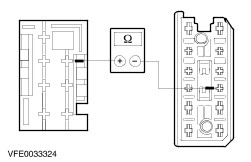
| B2: CHECK THE STEERING COLUMN MULTIFUNCTION SWITCH FOR PROPER FUNCTION |
| | 1 Ignition switch in position 0. |
| | 2 Disconnect steering column multifunction switch from connector C265. |
| | 3 SWITCH ON the turn signal lamps left-hand side. |
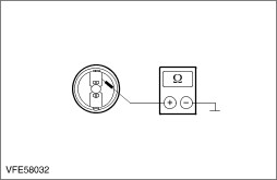
| | 4 Measure the resistance between steering column multifunction switch, connector C265, pin 3 and pin 5, component side. |
| | Is the resistance less than 2 ohms? Yes No INSTALL a new steering column multifunction switch. TEST the system for normal operation. |
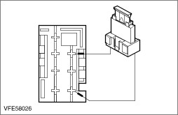
| B3: CHECK THE CIRCUIT (GN/BK) BETWEEN CJB AND STEERING COLUMN MULTIFUNCTION SWITCH FOR OPEN |
| | 1 Disconnect central junction box (CJB) from connector C1. |
| | 2 Measure the resistance between CJB, connector C1, pin 4, circuit (GN/BK), wiring harness side and steering column multifunction switch, connector C265, pin 3, circuit (GN/BK), wiring harness side. |
| | Is the resistance less than 2 ohms? Yes Vehicles before 11/2003: INSTALL a new CJB. TEST the system for normal operation. No LOCATE and REPAIR the open circuit between CJB and steering column multifunction switch, by using the wiring diagrams. TEST the system for normal operation. |
| B4: CHECK THE COMMON POWER SUPPLY OF THE TURN SIGNAL LAMPS LEFT-HAND SIDE FOR OPEN |
| | 1 Disconnect central junction box (CJB) from connector C7. |
| | 2 Measure the resistance between CJB, connector C7, pin 5, circuit (BK/WH), wiring harness side and ground. |
| | Is the resistance less than 10.000 ohms? Yes INSTALL a new CJB. TEST the system for normal operation. No LOCATE and REPAIR the open circuit between CJB and splice S82 by using the wiring diagrams. TEST the system for normal operation. |
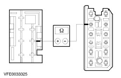
| B5: CHECK THE STEERING COLUMN MULTIFUNCTION SWITCH FOR PROPER FUNCTION |
| | 1 Ignition switch in position 0. |
| | 2 Disconnect steering column multifunction switch from connector C265. |
| | 3 SWITCH ON the turn signal lamps right-hand side. |
| | 4 Measure the resistance between steering column multifunction switch, connector C265, pin 11 and pin 5, component side. |
| | Is the resistance less than 2 ohms? Yes No INSTALL a new steering column multifunction switch. TEST the system for normal operation. |
| B6: CHECK THE CIRCUIT (GN) BETWEEN CJB AND STEERING COLUMN MULTIFUNCTION SWITCH FOR OPEN |
| | 1 Disconnect central junction box (CJB) from connector C1. |
| | 2 Measure the resistance between CJB, connector C1, pin 3, circuit (GN), wiring harness side and steering column multifunction switch, connector C265, pin 11, circuit (GN), wiring harness side. |
| | Is the resistance less than 2 ohms? Yes No LOCATE and REPAIR the open circuit (GN), between CJB and steering column multifunction switch. TEST the system for normal operation. |
| B7: CHECK THE COMMON POWER SUPPLY OF THE TURN SIGNAL LAMPS RIGHT-HAND SIDE FOR OPEN |
| | 1 Disconnect central junction box (CJB) from connector C7. |
| | 2 Measure the resistance between CJB, connector C7, pin 6, circuit (BK/GN), wiring harness side and ground. |
| | Is the resistance less than 10.000 ohms? Yes INSTALL a new CJB. TEST the system for normal operation. No LOCATE and REPAIR the open circuit between CJB and splice S83, by using the wiring diagrams. TEST the system for normal operation. |
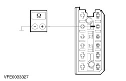
| B8: CHECK THE GROUND CONNECTION OF THE STEERING COLUMN MULTIFUNCTION SWITCH |
| | 1 Ignition switch in position 0. |
| | 2 Disconnect steering column multifunction switch from connector C265. |
| | 3 Measure the resistance between steering column multifunction switch, connector C265, pin 5, circuit (BN), wiring harness side and ground. |
| | Is the resistance less than 2 ohms? Yes INSTALL a new steering column multifunction switch. TEST the system for normal operation. No LOCATE and REPAIR the open circuit, between steering column multifunction switch and splice S78 (before 11/2002) or splice S1129 (as of 11/2002) by using the wiring diagrams. TEST the system for normal operation. |
| B9: DETERMINE THE FAULT CONDITION |
| | 1 Ignition switch in position II. |
| | 2 SWITCH ON the turn signal lamps left-hand side. |
| | 3 SWITCH ON the turn signal lamps right-hand side. |
| | 4 CHECK all turn signal lamps. |
| | Is the inoperative turn signal lamp located on the left-hand side? Yes - Front turn signal lamp, left-hand side and side turn signal lamp, left-hand side are inoperative, vehicles before 11/2003: GO to B10. - Front turn signal lamp, left-hand side and side turn signal lamp, left-hand side are inoperative, vehicles as of 11/2003: LOCATE and REPAIR the open circuit(s) between splice S17 and ground G3 by using the wiring diagrams. TEST the system for normal operation. - Front turn signal lamp, left-hand side is inoperative (conventional headlamp): GO to B11. - Front turn signal lamp, left-hand side is inoperative (high intensity discharge headlamps): GO to B13. - Side turn signal lamp, left-hand side, is inoperative: GO to B15. - Rear turn signal lamp, left-hand side is inoperative: GO to B17. No - Front turn signal lamp, right-hand side and side turn signal lamp, right-hand side are inoperative: GO to B19. - Front turn signal lamp, right-hand side is inoperative (conventional headlamp): GO to B20. - Front turn signal lamp, right-hand side is inoperative (high intensity discharge headlamp): GO to B22. - Side turn signal lamp, right-hand side is inoperative: GO to B24. - Rear turn signal lamp, right-hand side is inoperative: GO to B26. |
| B10: CHECK THE GROUND CONNECTION OF SPLICE S17 FOR OPEN |
| | 1 Ignition switch in position II. |
| | 2 SWITCH ON the parking lamps. |
| | 3 CHECK the parking lamp left-hand side. |
| | Is the parking lamp illuminated? Yes LOCATE and REPAIR the open circuit (BK/WH) between CJB and splice S82, by using the wiring diagrams. TEST the system for normal operation. No LOCATE and REPAIR the open circuit(s) between splice S17 and ground G3 by using the wiring diagrams. TEST the system for normal operation. |
| B11: CHECK THE VOLTAGE AT THE HEADLAMP LEFT-HAND SIDE |
| | 1 Ignition switch in position 0. |
| | 2 Disconnect headlamp left-hand side from connector C194. |
| | 3 Ignition switch in position II. |
| | 4 SWITCH ON the turn signal left-hand side. |
| | 5 Measure the voltage between headlamp left-hand side, connector C194, pin 6, circuit (BK/WH), wiring harness side and ground. |
| | Is alternating battery voltage indicated? Yes No LOCATE and REPAIR the open circuit between splice S82 and headlamp, by using the wiring diagrams. TEST the system for normal operation. |
| B12: CHECK THE GROUND CONNECTION OF THE HEADLAMP LEFT-HAND SIDE |
| | 1 Ignition switch in position 0. |
| | 2 Measure the resistance between headlamp left-hand side, connector C194, pin 8, circuit (BN), wiring harness side and ground. |
| | Is the resistance less than 2 ohms? Yes CHECK the headlamp, if necessary INSTALL a new one. TEST the system for normal operation. No LOCATE and REPAIR the open circuit between headlamp and splice S17 by using the wiring diagrams. TEST the system for normal operation. |
| B13: CHECK THE VOLTAGE AT THE HIGH INTENSITY DISCHARGE HEADLAMP LEFT-HAND SIDE |
| | 1 Ignition switch in position 0. |
| | 2 Disconnect headlamp left-hand side from connector C271. |
| | 3 Ignition switch in position II. |
| | 4 SWITCH ON the turn signal lamp left-hand side. |
| | 5 Measure the voltage between headlamp left-hand side, connector C271, pin 3, circuit (BK/WH), wiring harness side and ground. |
| | Is alternating battery voltage indicated? Yes No LOCATE and REPAIR the open circuit between splice S82 and headlamp by using the wiring diagrams. TEST the system for normal operation. |
| B14: CHECK THE GROUND CONNECTION OF THE HIGH INTENSITY DISCHARGE HEADLAMP LEFT-HAND SIDE |
| | 1 Ignition switch in position 0. |
| | 2 Measure the resistance between headlamp left-hand side, connector C271, pin 7, circuit (BN), wiring harness side and ground. |
| | Is the resistance less than 2 ohms? Yes CHECK the headlamp, if necessary INSTALL a new one. TEST the system for normal operation. No LOCATE and REPAIR the open circuit between headlamp and splice S17 by using the wiring diagrams. TEST the system for normal operation. |
| B15: CHECK THE VOLTAGE AT THE SIDE TURN SIGNAL LAMP LEFT-HAND SIDE |
| | 1 Ignition switch in position 0. |
| | 2 Disconnect side turn signal lamp, left-hand side from connector C384. |
| | 3 Ignition switch in position II. |
| | 4 SWITCH ON the turn signal left-hand side. |
| | 5 Measure the voltage between side turn signal lamp, left-hand side, connector C384, pin 2, circuit (BK/WH), wiring harness side and ground. |
| | Is alternating battery voltage indicated? Yes No LOCATE and REPAIR the open circuit between splice S82 and side turn signal lamp by using the wiring diagrams. TEST the system for normal operation. |
| B16: CHECK THE GROUND CONNECTION OF THE SIDE TURN SIGNAL LAMP LEFT-HAND SIDE |
| | 1 Ignition switch in position 0. |
| | 2 Measure the resistance between side turn signal lamp, left-hand side, connector C384, pin 1, circuit (BN), wiring harness side and ground. |
| | Is the resistance less than 2 ohms? Yes CHECK the side turn signal lamp, if necessary INSTALL a new one. TEST the system for normal operation. No LOCATE and REPAIR the open circuit between side turn signal lamp and splice S17 by using the wiring diagrams. TEST the system for normal operation. |
| B17: CHECK THE VOLTAGE AT THE TURN SIGNAL LAMP, REAR, LEFT-HAND SIDE |
| | 1 Ignition switch in position 0. |
| | 2 Disconnect rear lamp assembly, left-hand side from connector: . - Vehicles with fixed towbar: C553
|
| | 3 Ignition switch in position II. |
| | 4 SWITCH ON the turn signal left-hand side. |
| | 5 Measure the voltage between rear lamp assembly, left-hand side, connector: - Vehicles with fixed towbar: C553, pin 4, circuit (BK/WH), wiring harness side and ground.
- All other models: C261, pin 4, circuit (BK/WH), wiring harness side and ground.
|
| | Is alternating battery voltage indicated? Yes No - Vehicles before 11/2003: LOCATE and REPAIR the open circuit between CJB and rear lamp assembly, by using the wiring diagrams. TEST the system for normal operation. - Vehicles as of 11/2003: LOCATE and REPAIR the open circuit between splice S82 and rear lamp assembly, by using the wiring diagrams. TEST the system for normal operation. |
| B18: CHECK THE GROUND CONNECTION OF THE REAR LAMP ASSEMBLY LEFT-HAND SIDE |
| | 1 Ignition switch in position 0. |
| | 2 Measure the resistance between rear lamp assembly left-hand side, connector: - Vehicles with fixed towbar: C553, pin 2, circuit (GN), wiring harness side and ground.
- All other models: C261, pin 2, circuit (BN), wiring harness side and ground.
|
| | Is the resistance less than 2 ohms? Yes CHECK the rear lamp assembly, if necessary INSTALL a new one. TEST the system for normal operation. No LOCATE and REPAIR the open circuit between rear lamp assembly and splice S70 by using the wiring diagrams. TEST the system for normal operation. |
| B19: CHECK THE GROUND CONNECTION OF SPLICE S177 FOR OPEN |
| | 1 Ignition switch in position II. |
| | 2 SWITCH ON the parking lamps. |
| | 3 CHECK the parking lamps. |
| | Is the parking lamp right-hand side illuminated? Yes LOCATE and REPAIR the open circuit (BK/GN) between splice S83 and splice S84, by using the wiring diagrams. TEST the system for normal operation. No LOCATE and REPAIR the open circuit(s) between splice S177 and ground G4 by using the wiring diagrams. TEST the system for normal operation. |
| B20: CHECK THE VOLTAGE AT THE HEADLAMP RIGHT-HAND SIDE |
| | 1 Ignition switch in position 0. |
| | 2 Disconnect headlamp right-hand side from connector C195. |
| | 3 Ignition switch in position II. |
| | 4 SWITCH ON the turn signal right-hand side. |
| | 5 Measure the voltage between headlamp right-hand side, connector C195, pin 6, circuit (BK/GN), wiring harness side and ground. |
| | Is alternating battery voltage indicated? Yes No LOCATE and REPAIR the open circuit between splice S84 and headlamp, by using the wiring diagrams. TEST the system for normal operation. |
| B21: CHECK THE GROUND CONNECTION OF THE HEADLAMP RIGHT-HAND SIDE |
| | 1 Ignition switch in position 0. |
| | 2 Measure the resistance between headlamp right-hand side, connector C195, pin 8, circuit (BN), wiring harness side and ground. |
| | Is the resistance less than 2 ohms? Yes CHECK the headlamp, if necessary INSTALL a new one. TEST the system for normal operation. No LOCATE and REPAIR the open circuit between headlamp and splice S177 by using the wiring diagrams. TEST the system for normal operation. |
| B22: CHECK THE VOLTAGE AT THE HIGH INTENSITY DISCHARGE HEADLAMP RIGHT-HAND SIDE |
| | 1 Ignition switch in position 0. |
| | 2 Disconnect headlamp right-hand side from connector C272. |
| | 3 Ignition switch in position II. |
| | 4 SWITCH ON the turn signal right-hand side. |
| | 5 Measure the voltage between headlamp right-hand side, connector C272, pin 3, circuit (BK/GN), wiring harness side and ground. |
| | Is alternating battery voltage indicated? Yes No LOCATE and REPAIR the open circuit between splice S84 and headlamp, by using the wiring diagrams. TEST the system for normal operation. |
| B23: CHECK THE GROUND CONNECTION OF THE HIGH INTENSITY DISCHARGE HEADLAMP RIGHT-HAND SIDE |
| | 1 Ignition switch in position 0. |
| | 2 Measure the resistance between headlamp right-hand side, connector C272, pin 7, circuit (BN), wiring harness side and ground. |
| | Is the resistance less than 2 ohms? Yes CHECK the headlamp, if necessary INSTALL a new one. TEST the system for normal operation. No LOCATE and REPAIR the open circuit between headlamp and splice S177 by using the wiring diagrams. TEST the system for normal operation. |
| B24: CHECK THE VOLTAGE AT THE SIDE TURN SIGNAL LAMP RIGHT-HAND SIDE |
| | 1 Ignition switch in position 0. |
| | 2 Disconnect side turn signal lamp, right-hand side from connector C380. |
| | 3 Ignition switch in position II. |
| | 4 SWITCH ON the turn signal lamp right-hand side. |
| | 5 Measure the voltage between side turn signal lamp, right-hand side, connector C380, pin 2, circuit (BK/GN), wiring harness side and ground. |
| | Is alternating battery voltage indicated? Yes No LOCATE and REPAIR the open circuit between splice S84 and side turn signal lamp, by using the wiring diagrams. TEST the system for normal operation. |
| B25: CHECK THE GROUND CONNECTION OF THE SIDE TURN SIGNAL LAMP RIGHT-HAND SIDE |
| | 1 Ignition switch in position 0. |
| | 2 Measure the resistance between side turn signal lamp, right-hand side, connector C380, pin 1, circuit (BN), wiring harness side and ground. |
| | Is the resistance less than 2 ohms? Yes CHECK the side turn signal lamp, if necessary INSTALL a new one. TEST the system for normal operation. No LOCATE and REPAIR the open circuit between side turn signal lamp and splice S177 by using the wiring diagrams. TEST the system for normal operation. |
| B26: CHECK THE VOLTAGE AT THE TURN SIGNAL LAMP, REAR, RIGHT-HAND SIDE |
| | 1 Ignition switch in position 0. |
| | 2 Disconnect rear lamp assembly right-hand side from connector: . - Vehicles with fixed towbar: C554, pin 1, circuit (BK/GN), wiring harness side and ground.
- All other models: C262, pin 1, circuit (BK/GN), wiring harness side and ground.
|
| | 3 Ignition switch in position II. |
| | 4 SWITCH ON the turn signal right-hand side. |
| | 5 Measure the voltage between rear lamp assembly, right-hand side, connector: - Vehicles with fixed towbar: C554, pin 1, circuit (BK/GN), wiring harness side and ground.
- All other models: C262, pin 1, circuit (BK/GN), wiring harness side and ground.
|
| | Is alternating battery voltage indicated? Yes No LOCATE and REPAIR the open circuit between splice S83 and rear lamp assembly, by using the wiring diagrams. TEST the system for normal operation. |
| B27: CHECK THE GROUND CONNECTION OF THE REAR LAMP ASSEMBLY RIGHT-HAND SIDE |
| | 1 Ignition switch in position 0. |
| | 2 Measure the resistance between rear lamp assembly right-hand side, connector: - Vehicles with fixed towbar: C554, pin 3, circuit (BN), wiring harness side and ground.
- All other models: C262, pin 3, circuit (BN), wiring harness side and ground.
|
| | Is the resistance less than 2 ohms? Yes CHECK the rear lamp assembly, if necessary INSTALL a new one. TEST the system for normal operation. No LOCATE and REPAIR the open circuit between rear lamp assembly and ground G13 by using the wiring diagrams. TEST the system for normal operation. |