| Diagnosis and Testing Refer to Wiring Diagrams Section 417-01, for schematic and connector information. Special Tool(s) | | Terminal probe kit 29-011A | Inspection and Verification NOTE:The generic electronic module (GEM) is part of the central junction box (CJB). NOTE:If a new GEM module is being installed, the new module must be configured following installation. For this purpose, the vehicle-specific data is read out of the module to be changed using WDS and is transferred to the new module.REFER to: Module Configuration (418-01 Module Configuration, General Procedures), Generic Electronic Module (GEM) (419-10 Multifunction Electronic Modules, Diagnosis and Testing). NOTE:If a new PCM module is being installed, the new module must be programmed following installation. For this purpose, the vehicle-specific data is read out of the module to be changed using WDS and is transferred to the new module.
REFER to: Module Configuration (418-01 Module Configuration, General Procedures).
NOTE:Before reading out the vehicle-specific data make sure that all electrical connections in the vehicle are reconnected so that the module and WDS can communicate correctly. - Verify the customer concern.
- Visually inspect for obvious signs of electrical damage.
Visual Inspection Chart | Mechanical | Electrical | - Stop lamp switch adjustment
| - Fuse(s)
- Bulb(s)
- Electrical connector(s)
- Switch(es)
- Wiring harness
| - If an obvious cause for an observed or reported concern is found, correct the cause (if possible) before proceeding to the next step.
- If the concern is not visually evident, verify the symptom and refer to the Symptom Chart.
Symptom Chart Symptom Chart | Symptom | Possible Sources | Action | | The stoplamps are inoperative | * Fuse * Circuit(s) * Stoplamp switch * Stoplamp/brake pedal position switch * Stoplamp relay * Electronic stability program (ESP) module * Central Junction Box (CJB) | * | | One or more stoplamps are inoperative | * Circuit(s) * Rear lamp assembly * High mounted stoplamp * Central Junction Box (CJB) | * | | The Stoplamps are on continuously | * Circuit(s) * Stoplamp switch * Stoplamp/brake pedal position switch * Electronic stability program (ESP) module * Automatic transmission control module * Electric shift transfer case assembly * ABS module * Powertrain control module (PCM) * Central Junction Box (CJB) * Trailer socket | * | Pinpoint Tests NOTE:Use a digital multimeter for all electrical measurements. | PINPOINT TEST A : THE STOPLAMPS ARE INOPERATIVE | | TEST CONDITIONS | DETAILS/RESULTS/ACTIONS | | A1: CHECK FUSE F15 (10 A) (CJB) | | | 1 Ignition switch in position 0. | | | 2 Disconnect fuse F15 (10 A) (CJB). | | | 3 CHECK fuse F15 (10 A) (CJB). | | | Is the fuse OK? Yes No INSTALL a new fuse F15 (10 A) (CJB). TEST the system for normal operation. If the fuse blows again, LOCATE and REPAIR the short to ground by using the wiring diagrams. TEST the system for normal operation. | | A2: CHECK THE VOLTAGE AT FUSE F15 ( 10 A) (CJB) | | | 1 Connect fuse F15 (10 A) (CJB). | | | 2 Ignition switch in position II. | | | 3 Measure the voltage between fuse F15 (10 A) (CJB) and ground. | | | Is battery voltage indicated? Yes - Vehicles with 2.0L/2.3L DOHC engines: GO to A3. No REPAIR the power supply of fuse F15 (10 A) (CJB) by using the wiring diagrams. TEST the system for normal operation. If necessary INSTALL a new CJB. TEST the system for normal operation. | | A3: CHECK THE VOLTAGE AT THE STOPLAMP SWITCH | | | 1 Ignition switch in position 0. | | | 2 Disconnect stoplamp switch from connector C172. | | | 3 Ignition switch in position II. | | | 4 Measure the voltage between stoplamp switch, connector C172, pin 2, circuit (RD/YE), wiring harness side and ground. | | | Is battery voltage indicated? Yes No LOCATE and REPAIR the open circuit (RD/YE), between fuse F15 (CJB) and stoplamp switch by using the wiring diagrams. If necessary INSTALL a new CJB. TEST the system for normal operation. | | A4: CHECK THE STOPLAMP SWITCH | | | 1 Ignition switch in position 0. | | | 2 Connect a fused jumper wire (10 A) at the stoplamp switch, connector C172, between pin 2, circuit (RD/YE) and pin 1, circuit (BK/RD), wiring harness side. | | | 3 Ignition switch in position II. | | | 4 CHECK the stoplamps. | | | Are the stoplamps illuminated? Yes INSTALL a new stoplamp switch. TEST the system for normal operation. No - Vehicle without ESP: LOCATE and REPAIR the open circuit (BK/RD) or (RD/GY), between stoplamp switch and splice S1, by using the wiring diagrams. TEST the system for normal operation. | | A5: CHECK THE VOLTAGE AT THE STOPLAMP/BRAKE PEDAL POSITION SWITCH | | | 1 Ignition switch in position 0. | | | 2 Disconnect stoplamp/brake pedal position switch. - Vehicles with 1.9 TDI engines: from connector C354
- Vehicles with 2.8L CD-V6 24V engines: from connector C153
| | | 3 Ignition switch in position II. | | | 4 Measure the voltage between stoplamp/brake pedal position switch: - Vehicles with 1.9 TDI engines: connector C354, pin 1, circuit (RD/YE), wiring harness side and ground.
- Vehicles with 2.8L CD-V6 24V engines: connector C153, pin 1, circuit (RD/YE), wiring harness side and ground.
| | | Is battery voltage indicated? Yes No LOCATE and REPAIR the open circuit (RD/YE), between fuse F15 and stoplamp/brake pedal position switch by using the wiring diagrams. If necessary INSTALL a new CJB. TEST the system for normal operation. | | A6: CHECK THE STOPLAMP/BRAKE PEDAL POSITION SWITCH | | | 1 Ignition switch in position 0. | | | 2 Connect a fused jumper wire (10 A) at the stoplamp/brake pedal position switch: - Vehicles with 1.9 TDI engines: connector C354, between pin 1, circuit (RD/YE) and pin 4, circuit (BK/RD), wiring harness side.
- Vehicles with 2.8L CD-V6 24V engines: connector C153, between pin 1, circuit (RD/YE) and pin 4, circuit (BK/RD), wiring harness side.
| | | 3 Ignition switch in position II. | | | 4 CHECK the stoplamps. | | | Do the stoplamps illuminate? Yes INSTALL a new stoplamp/brake pedal position switch. TEST the system for normal operation. No - Vehicle without ESP: LOCATE and REPAIR the open circuit (BK/RD) or (RD/GY), between stoplamp/brake pedal position switch and splice S1, by using the wiring diagrams. TEST the system for normal operation. | | A7: CHECK THE VOLTAGE AT THE STOPLAMP RELAY | NOTE:Make sure that the jumper wire at the stoplamp/brake pedal position switch is still connected. | | | 1 Ignition switch in position 0. | | | 2 Disconnect stoplamp relay from socket C14. | | | 3 Ignition switch in position II. | | | 4 Measure the voltage between stoplamp relay, socket C14, pin 2, circuit (BK/GY), CJB side and ground. | | | Is battery voltage indicated? Yes No LOCATE and REPAIR the open circuit(s) (BK/RD) or (BK/GY), between stoplamp/brake pedal position switch and stoplamp relay by using the wiring diagrams. TEST the system for normal operation. | | A8: CHECK THE CIRCUITS (RD/GY), (BK/YE) AND (BK/RD) FOR OPEN | NOTE:Make sure that the jumper wire at the stoplamp/brake pedal position switch is still connected. | | | 1 Ignition switch in position 0. | | | 2 Connect a fused jumper wire (10 A) at the stoplamp relay: - Vehicles before 05/2004: socket C14, between pin 2, circuit (BK/GY) and pin 5, circuit (RD/GY), CJB side.
- Vehicles as of 05/2004: socket C14, between pin 2, circuit (BK/GY) and pin 5, circuit (BK/RD), CJB side.
| | | 3 Ignition switch in position II. | | | 4 CHECK the stoplamps. | | | Are the stoplamps illuminated? Yes No LOCATE and REPAIR the open circuit(s), between stoplamp relay and splice S1, by using the wiring diagrams. TEST the system for normal operation. | | A9: CHECK THE CIRCUIT (BU) BETWEEN STOPLAMP RELAY AND ELECTRONIC STABILITY PROGRAM (ESP) MODULE FOR SHORT TO GROUND | | | 1 Ignition switch in position 0. | | | 2 Disconnect electronic stability program (ESP) module. - Vehicles before 11/2002: from connector C59
- Vehicles as of 11/2002: from connector C635
| | | 3 Measure the resistance between stoplamp relay, socket C14, between pin 4, circuit (BU), CJB side and ground. | | | Is the resistance greater than 10.000 ohms? Yes No LOCATE and REPAIR the short to ground in circuit between stoplamp relay and electronic stability program (ESP) module by using the wiring diagrams. TEST the system for normal operation. | | A10: CHECK THE STOPLAMP RELAY FOR PROPER FUNCTION | | | 1 Ignition switch in position 0. | | | 2 CHECK the stoplamp relay according to the Component Test attached to this procedure. | | | Is the stoplamp relay OK? Yes CHECK the electronic stability program (ESP) module by using the WDS. TEST the system for normal operation. No INSTALL a new stoplamp relay. TEST the system for normal operation. | | PINPOINT TEST B : ONE OR MORE STOPLAMPS ARE INOPERATIVE | | TEST CONDITIONS | DETAILS/RESULTS/ACTIONS | | B1: DETERMINE THE FAULT CONDITION | | | 1 Ignition switch in position 0. | | | 2 Disconnect stoplamp/brake pedal position switch. - Vehicles with 1.9 TDI engines: from connector C354
- Vehicles with 2.8L CD-V6 24V engines: from connector C153
- Vehicles with 2.0L/2.3L DOHC engines: from connector C172
| | | 3 Connect a fused jumper wire (10 A) at the stoplamp/brake pedal position switch: - Vehicles with 1.9 TDI engines: connector C354, between pin 1, circuit (RD/YE) and pin 4, circuit (BK/RD), wiring harness side.
- Vehicles with 2.8L CD-V6 24V engines: connector C153, between pin 1, circuit (RD/YE) and pin 4, circuit (BK/RD), wiring harness side.
- Vehicles with 2.0L/2.3L DOHC engines: connector C172, between pin 2, circuit (RD/YE) and pin 1, circuit (BK/RD), wiring harness side.
| | | 4 Ignition switch in position II. | | | 5 CHECK the stoplamps. | | | Is the high mounted stoplamp inoperative? Yes No - The stoplamps left-hand side and right-hand side are inoperative: GO to B4. - The stoplamp left-hand side is inoperative: GO to B8. - The stoplamp right-hand side is inoperative: GO to B5. | | B2: CHECK THE VOLTAGE AT THE HIGH MOUNTED STOPLAMP | NOTE:The fused jumper wire remains connected in this step. | | | 1 Ignition switch in position 0. | | | 2 Disconnect high mounted stoplamp from connector C348. | | | 3 Ignition switch in position II. | | | 4 Measure the voltage between high mounted stoplamp, connector C348, pin 1, circuit (BK/RD), wiring harness side and ground. | | | Is battery voltage indicated? Yes No LOCATE and REPAIR the open circuit between high mounted stoplamp and splice S1 by using the wiring diagrams. TEST the system for normal operation. | | B3: CHECK THE GROUND CONNECTION OF THE HIGH MOUNTED STOPLAMP | | | 1 Ignition switch in position 0. | | | 2 Measure the resistance between high mounted stoplamp, connector C348, pin 2, circuit (BN), wiring harness side and ground. | | | Is the resistance less than 2 ohms? Yes INSTALL a new high mounted stoplamp. TEST the system for normal operation. No LOCATE and REPAIR the open circuit between high mounted stoplamp and splice S66 by using the wiring diagrams. TEST the system for normal operation. | | B4: CHECK THE VOLTAGE AT THE CJB | NOTE:The fused jumper wire remains connected in this step. | | | 1 Ignition switch in position 0. | | | 2 Disconnect central junction box (CJB) from connector C5. | | | 3 Ignition switch in position II. | | | 4 Measure the voltage between CJB, connector C5, pin 4, circuit (RD/BK), wiring harness side and ground. | | | Is battery voltage indicated? Yes INSTALL a new CJB. TEST the system for normal operation. No LOCATE and REPAIR the open circuit between splice S1 and CJB by using the wiring diagrams. TEST the system for normal operation. | | B5: CHECK THE VOLTAGE AT THE STOPLAMP RIGHT-HAND SIDE | NOTE:The fused jumper wire remains connected in this step. | | | 1 Ignition switch in position 0. | | | 2 Disconnect rear lamp assembly right-hand side from connector. - Vehicles with fixed towbar: C554
| | | 3 Measure the voltage between: - Vehicles with fixed towbar: Rear lamp assembly right-hand side, connector C554, pin 2, circuit (GN), wiring harness side and ground.
- All other models: Rear lamp assembly right-hand side, connector C262, pin 2, circuit (BK/RD), wiring harness side and ground.
| | | Is battery voltage indicated? Yes No | | B6: CHECK THE CJB | NOTE:The fused jumper wire remains connected in this step. | | | 1 Ignition switch in position 0. | | | 2 Connect rear lamp assembly right-hand side to connector. - Vehicles with fixed towbar: C554
| | | 3 Disconnect central junction box (CJB) from connector C5. | | | 4 Connect a fused jumper wire (10 A) at the CJB, connector C5, between pin 4, circuit (RD/BK) and pin 3, circuit (BK/RD), wiring harness side. | | | 5 Ignition switch in position II. | | | 6 CHECK the stoplamp right-hand side. | | | Does the stoplamp right-hand side illuminate? Yes INSTALL a new CJB. TEST the system for normal operation. No LOCATE and REPAIR the open circuit (BK/RD), between CJB and rear lamp assembly right-hand side by using the wiring diagrams. TEST the system for normal operation. | | B7: CHECK THE GROUND CONNECTION OF THE STOPLAMP RIGHT-HAND SIDE | | | 1 Ignition switch in position 0. | | | 2 Measure the resistance between: - Vehicles with fixed towbar: Rear lamp assembly right-hand side, connector C554, pin 3, circuit (BN), wiring harness side and ground.
- All other models: Rear lamp assembly right-hand side, connector C262, pin 3, circuit (BN), wiring harness side and ground.
| | | Is the resistance less than 2 ohms? Yes INSTALL a new rear lamp assembly. TEST the system for normal operation. No LOCATE and REPAIR the open circuit between rear lamp assembly right-hand side and splice S71 by using the wiring diagrams. TEST the system for normal operation. | | B8: CHECK THE VOLTAGE AT THE STOPLAMP LEFT-HAND SIDE | NOTE:The fused jumper wire remains connected in this step. | | | 1 Ignition switch in position 0. | | | 2 Disconnect rear lamp assembly left-hand side from connector. - Vehicles with fixed towbar: C553
| | | 3 Ignition switch in position II. | | | 4 Measure the voltage between: - Vehicles with fixed towbar: Rear lamp assembly left-hand side, connector C553, pin 3, circuit (BK/RD), wiring harness side and ground.
- All other models: Rear lamp assembly left-hand side, connector C261, pin 3, circuit (BK/WH), wiring harness side and ground.
| | | Is battery voltage indicated? Yes No | | B9: CHECK THE CJB | NOTE:The fused jumper wire remains connected in this step. | | | 1 Ignition switch in position 0. | | | 2 Connect rear lamp assembly left-hand side to connector. - Vehicles with fixed towbar: C553
| | | 3 Disconnect central junction box (CJB) from connector C5. | | | 4 Connect a fused jumper wire (10 A) at the CJB, connector C5, between pin 4, circuit (RD/BK) and pin 5, circuit (BK/WH), wiring harness side. | | | 5 Ignition switch in position II. | | | 6 CHECK the stoplamp left-hand side. | | | Does the stoplamp left-hand side illuminate? Yes INSTALL a new CJB. TEST the system for normal operation. No LOCATE and REPAIR the open circuit (BK/WH), between CJB and rear lamp assembly left-hand side by using the wiring diagrams. TEST the system for normal operation. | | B10: CHECK THE GROUND CONNECTION OF THE STOPLAMP LEFT-HAND SIDE | | | 1 Ignition switch in position 0. | | | 2 Measure the resistance between: - Vehicles with fixed towbar: Rear lamp assembly left-hand side, connector C553, pin 2, circuit (GN), wiring harness side and ground.
- All others models: Rear lamp assembly left-hand side, connector C261, pin 2, circuit (BN), wiring harness side and ground.
| | | Is the resistance less than 2 ohms? Yes INSTALL a new rear lamp assembly. TEST the system for normal operation. No LOCATE and REPAIR the open circuit between rear lamp assembly left-hand side and splice S70 by using the wiring diagrams. TEST the system for normal operation. | | PINPOINT TEST C : THE STOPLAMPS ARE ON CONTINUOUSLY | | TEST CONDITIONS | DETAILS/RESULTS/ACTIONS | | C1: CHECK THE STOPLAMP SWITCH | | | 1 Ignition switch in position 0. | | | 2 Disconnect stoplamp/brake pedal position switch from connector. - 1.9 TDI unit injection: C354
| | | 3 Ignition switch in position II. | | | 4 CHECK the stoplamps. | | | Are the stoplamps on continuously? Yes No INSTALL a new stoplamp/brake pedal position switch. TEST the system for normal operation. | | C2: DETERMINE THE EQUIPMENT OF THE VEHICLE | | | 1 Ignition switch in position 0. | | | 2 Connect stoplamp/brake pedal position switch to connector. - 1.9 TDI unit injection: C354
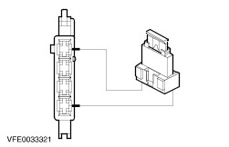
| | | Is the vehicle equipped with automatic transmission? Yes No | | C3: RULE OUT AUTOMATIC TRANSMISSION CONTROL MODULE AS POSSIBLE CAUSE FOR A SHORT TO POWER | | | 1 Disconnect fuse F5 (15 A) (CJB). | | | 2 Disconnect fuse F17 (10 A) (CJB). | | | 3 Ignition switch in position II. | | | 4 CHECK the stoplamps. | | | Are the stoplamps on continuously? Yes No INSTALL a new automatic transmission control module. TEST the system for normal operation. | | C4: DETERMINE THE EQUIPMENT OF THE VEHICLE | | | 1 Determine the equipment of the vehicle. | | | Is the vehicle equipped with 6-speed manual transmission? Yes No | | C5: RULE OUT ELECTRIC SHIFT TRANSFER CASE ASSEMBLY AS POSSIBLE CAUSE FOR A SHORT TO POWER | | | 1 Disconnect fuse F5 (15 A) (CJB). | | | 2 Ignition switch in position II. | | | 3 CHECK the stoplamps. | | | Are the stoplamps on continuously? Yes No INSTALL a new electric shift transfer case assembly . TEST the system for normal operation. | | C6: DETERMINE THE EQUIPMENT OF THE VEHICLE | | | 1 Ignition switch in position 0. | | | Is the vehicle equipped with ABS or ESP? Yes No | | C7: RULE OUT ABS MODULE OR ELECTRONIC STABILITY PROGRAM (ESP) MODULE AS POSSIBLE CAUSE FOR A SHORT TO POWER | | | 1 Disconnect fuse F3 (5 A) (CJB). | | | 2 Disconnect fuse F101 (30 A) (BJB). | | | 3 Disconnect fuse F102 (30 A) (BJB). | | | 4 Ignition switch in position II. | | | 5 CHECK the stoplamps. | | | Are the stoplamps on continuously? Yes No INSTALL a new ABS module/electronic stability program (ESP) module. TEST the system for normal operation. | | C8: DETERMINE THE EQUIPMENT OF THE VEHICLE | | | 1 Ignition switch in position 0. | | | Is the vehicle equipped with 2.0L/2.3L DOHC engines? Yes No | | C9: RULE OUT POWERTRAIN CONTROL MODULE (PCM) AS POSSIBLE CAUSE FOR A SHORT TO POWER | | | 1 Disconnect fuse F4 (10 A) (CJB). | | | 2 Disconnect 2.8L CD-V6 24V engines only: fuse F13 (3 A) (CJB). | | | 3 Disconnect 1.9 TDI engines only: fuse F14 (25 A) (CJB). | | | 4 Disconnect 1.9 TDI engines only: fuse F34 (10 A) (CJB). | | | 5 Ignition switch in position II. | | | 6 CHECK the stoplamps. | | | Are the stoplamps on continuously? Yes No INSTALL a new powertrain control module (PCM). TEST the system for normal operation. | | C10: DETERMINE THE EQUIPMENT OF THE VEHICLE | | | 1 Ignition switch in position 0. | | | Is the vehicle equipped with ESP? Yes No | | C11: ISOLATE THE SHORT TO POWER CIRCUIT | | | 1 Disconnect stoplamp relay from socket C14. | | | 2 Ignition switch in position II. | | | 3 CHECK the stoplamps. | | | Are the stoplamps on continuously? Yes No LOCATE and REPAIR the short to power in circuits connected with splice S2, by using the wiring diagrams. TEST the system for normal operation. | | C12: ISOLATE THE SHORT TO POWER CIRCUIT | | | 1 Ignition switch in position 0. | | | 2 Connect with ESP only: stoplamp relay to socket C14. | | | 3 Disconnect central junction box (CJB) from connector C5. | | | 4 Ignition switch in position II. | | | 5 CHECK the stoplamps. | | | Is one stoplamp on continuously? Yes - The high mounted stoplamp is on continuously: LOCATE and REPAIR the short to power in circuits connected with splice S1, by using the wiring diagrams (vehicles with a detachable towbar, CHECK the trailer socket). TEST the system for normal operation. - The stoplamp left-hand side is on continuously: LOCATE and REPAIR the short to power in circuit (BK/WH) or (BK/RD), connected with the CJB, connector C5, pin 5, by using the wiring diagrams (vehicles with a fixed towbar, CHECK the trailer socket). TEST the system for normal operation. - The stoplamp right-hand side: LOCATE and REPAIR the short to power in circuit (BK/RD) or (GN), connected with the CJB, connector C5, pin 3, by using the wiring diagrams. TEST the system for normal operation. No INSTALL a new CJB. TEST the system for normal operation. | Component Test: Stoplamp relay - CHECK the contacts in the unswitched state:
- Measure the resistance at the stoplamp relay, between pin 2 and pin 5, component side.
- CHECK the contacts in the switched state:
- Using a fused test cable (3 A), connect pin 6 of the stoplamp relay, component side, to the battery positive terminal.
- Using a test cable, connect pin 4 of the stoplamp relay, component side, to the battery negative terminal.
- Measure the resistance at the stoplamp relay, between pin 2 and pin 5, component side.
- Is the resistance greater than 10.000 ohms?
1. If yes, then the stoplamp relay is OK. 2. If no, INSTALL a new stoplamp relay. |