| Removal Special Tool(s) | | Remover, Halfshaft 308-237 (16-087) | | | Remover, Halfshaft 308-256 (16-089) | | | Support Bar, Engine 303-290 (21-140) | | | Adapter for 303-290 303-290-01 (21-140-01) | | | Adapter for 303-290 303-290-03 (21-140-03) | General Equipment Engine lifting eye Transmission jack Auxiliary plugs Retaining straps Materials Name Specification Manual transmission fluid WSD-M2C200-C Cable ties Removal All Vehicles | | -
NOTE:The position descriptions for the engine mountings and the engine roll restrictor are given looking from the transaxle towards the engine. | | | -
Remove the battery tray. - Remove the cable ties.
- Remove the bolts.
| Vehicles with 1.6L engine | | -
Remove the air cleaner intake pipe. | Vehicles with diesel engine | | -
Remove the air cleaner intake pipe. - Remove the air cleaner intake from the intake manifold.
- Detach the air cleaner intake pipe from the retaining clip.
- Remove the air cleaner housing.
- Remove the air cleaner intake pipe from the resonator hose.
| All vehicles | | -
NOTE:Use an Allen key to prevent the piston rod turning. Loosen the left-hand and the right-hand suspension strut nut five turns. | | | -
WARNING:Escaping brake fluid. Do not allow brake fluid to come into contact with the skin or the eyes. If brake fluid does come into contact with the skin or the eyes, rinse the affected areas with water immediately. Failure to follow these instructions may result in personal injury. CAUTION:If brake fluid is spilt on the paintwork, the affected area must be immediately washed down with cold water. Disconnect the high-pressure line from the clutch slave cylinder. | Vehicles with 1.6L engine | | -
Disconnect the electrical connectors. - Disconnect the heated oxygen sensor (HO2S) electrical connector
- Disconnect the ignition coil electrical connector
- Disconnect the powertrain control module (PCM) electrical connector
- Disconnect the vehicle speed sensor (VSS) electrical connector.
| | | -
Remove the transaxle upper flange bolts with ground cable and the hose. - Remove the ground cable flange bolt
- Disconnect the generator electrical connector
- Disconnect the starter motor electrical connector
- Detach the transaxle ventilation hose
| | | -
Remove the transaxle upper flange bolts. | Vehicles with diesel engine | | -
Remove the transaxle upper flange bolts with ground cable. | | | -
Using the special tools support the engine and transaxle assembly. - Using the special tool slightly raise the .
| Vehicles with 1.6L engine | | -
Install an engine (cylinder No. 4) using the existing thread in the cylinder head. | | | -
Using the special tools support the engine and transaxle assembly. | All vehicles | | -
Remove the engine rear mounting bracket. | Vehicles with diesel engine | | -
Remove the engine front mounting bracket. | All vehicles | | -
Disconnect the reversing lamp switch electrical connector. | | | -
Disconnect the speedometer drive cable from the transaxle. | Vehicles with diesel engine | | -
Remove the halfshaft heat shield. | Vehicles with 1.6L engine | | -
Remove the halfshaft heat shield. | | | -
Remove the three way catalytic converter (TWC) from the exhaust manifold and secure it to one side. - Remove the nuts.
- Detach the hanger insulator.
- Remove and discard the gasket.
| All vehicles | | -
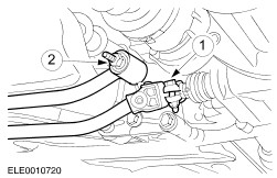
Disconnect the shift rod and shift rod stabilizer. - Disconnect the shift rod
- Disconnect the shift rod stabilizer
| | | -
NOTE:Do not disconnect the starter motor. Remove the starter motor bolts retaining and secure the starter motor to one side and the left-hand transaxle flange bolt. | | | -
Remove the lower arm ball joints on both sides (left-hand side shown). | | | -
Remove the constant velocity joint boot clamp. | | | -
CAUTION:The inner joint must not be bent at more than 18 degrees, the outer joint must not be bent at more than 45 degrees. NOTE:Remove the grease filling. Remove the halfshafts on both sides (left-hand side shown, right-hand side similar). Secure halshafts with cable ties. | | | -
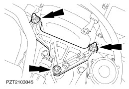
NOTE:The engine roll restrictor is under tension. Remove the engine roll restrictor. | | | -
Using the special tools, lower the transaxle. | Vehicles with 1.6L engine | | -
Push the engine forward and position a wooden block (260 mm) between the crossmember and the oil pan. | All vehicles | | -
Remove the transaxle right-hand flange bolts. | | | -
Remove the transaxle lower flange bolts. | | | -
NOTE:Secure the transaxle with a retaining strap and support it by using a transmission jack. Withdraw the transaxle from the engine and remove it. | |