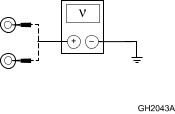
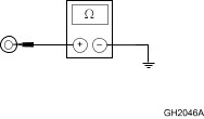
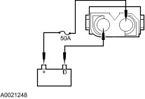
| Diagnosis and Testing Refer to Wiring Diagrams Section 206-09, for schematic and connector information. Special Tool(s) | | 73III Digital Multimeter 105-R0057 or equivalent | | | FLUKE 88 Digital Multimeter 105-R0053 or equivalent | | | EEC-IV 60-Pin Breakout Box 418-005 (014-00322) (T83L-50-EEC-IV) or equivalent | | | Worldwide Diagnostic System (WDS) 418-F224, New Generation STAR (NGS) Tester 418-F052, or equivalent scan tool | | | Anti-Lock Brake Adapter 418-063 (T97P-50-ALA) | Principles of Operation The ABS operates as follows: - When the brakes are applied, fluid is forced from the brake master cylinder outlet ports to the HCU inlet ports. This pressure is transmitted through four normally open solenoid valves contained inside the HCU and then through the outlet ports of the HCU to each wheel.
The electronic brake distribution (EBD) operates as follows: - The EBD control system detects the front/rear wheel slip according to the signal of ABS wheel speed sensors. If the rear wheel slip increases beyond a preset limit in proportion to the front wheel, the ABS HU/CU optimally reduces the brake fluid to the rear wheels. Brake force can, therefore, be proportioned optimally according to vehicle load and road surface conditions. The EBD control changes the distribution rate of the brake fluid pressure to the rear wheel slip. If the ABS control conditions are satisfied, EBD control is stopped and ABS control takes priority.
- If the ABS/EBD brake control module senses a wheel is about to lock, based on anti-lock brake sensor data, it closes the normally open solenoid valve for that circuit. This prevents any more fluid from entering that circuit.
- The anti-lock brake control module then looks at the anti-lock brake sensor signal from the affected wheel(s) again.
- If that wheel(s) is still decelerating, it opens the closed solenoid valve for that circuit.
- Once the affected wheel comes back up to speed, the anti-lock brake control module returns the valves to their normal condition, allowing fluid to flow to the affected brake.
- The ABS/EBD control module monitors the electromechanical components of the system.
- A malfunction in the ABS/EBD system will cause the ABS/EBD module to shut off or inhibit the system. However, normal power-assisted braking remains.
- Malfunctions are indicated by a yellow ABS warning indicator in the instrument cluster.
- A malfunction in the EBD function will cause the ABS control module to inhibit the function of the rear brake force distribution. In the event that EBD control stops, the rear wheels may lock before the front wheels, causing the vehicle to skid.
- Malfunctions are indicated by a red brake system warning light in the instrument cluster.
- The anti-lock brake and EBD system is self-monitoring. When the ignition switch is turned to the RUN position, the anti-lock brake and EBD control module will carry out a preliminary self-check on the anti-lock electrical system indicated by a three-second illumination of the yellow ABS warning indicator and the red brake warning indicator (if the parking brake is unapplied) in the instrument cluster.
- During vehicle operation, including normal and anti-lock braking, the anti-lock brake control module monitors all electrical anti-lock functions and some hydraulic operations.
- Each time the vehicle is driven, as soon as vehicle speed reaches approximately 20 km/h (12 mph), the anti-lock brake control module turns on the pump motor for approximately one-half second. At this time, a mechanical noise may be heard. This is a normal function of the self-check by the anti-lock brake control module.
- Pedal pulsation coupled with noise while braking on loose gravel, bumps, wet or snowy roads is normal and indicates correct functioning of the vehicle's anti-lock brake control system.
Hydraulic Control Unit The HCU consists of the following components: - brake pressure control valve block
- pump motor
New brake pressure control valve block and pump motor are installed as an assembly. Anti-Lock Brake Control Module NOTE:The 4x2 service replacement module cannot be interchanged with the 4x4 module. The service replacement 4x4 module is interchangeable with the 4x2 module. The anti-lock brake control module is mounted to the HCU. It is an on-board diagnostic, non-repairable unit consisting of two microprocessors and the necessary circuitry for their operation. The anti-lock brake control module monitors system operation during normal driving as well as during anti-lock braking. Anti-lock brake module operation is as follows: - Under normal driving conditions, the microprocessor produces short test pulses to the solenoid valves that check the electrical system without any mechanical reaction.
- Impending wheel lock conditions trigger signals from the anti-lock brake control module that open and close the appropriate solenoid valves. This results in moderate pulsations in the brake pedal.
- The anti-lock brake module used in 4x4 application includes a G-sensor. It detects vehicle movement during a brake lockup event that is transferred to other wheels through the powertrain.
During normal braking, the brake pedal feel is identical to a standard brake system. Most faults that occur in the anti-lock brake system will be stored as a diagnostic trouble code (DTC) in the keep-alive memory of the anti-lock brake control module. The DTCs can be retrieved by following the on-board diagnostic procedures. Anti-Lock Brake Sensor NOTE:Any time an anti-lock brake sensor is removed, thoroughly clean the mounting surfaces. On front anti-lock brake sensors, apply High-Temperature 4x4 Front Axle and Wheel Bearing Grease. The anti-lock brake system uses four "active" sensors and four sensor indicators to detect the speed of each wheel. The teeth on the sensor indicator rotate past the stationary sensor at wheel speed. As the teeth pass the sensor, a digital input signal is generated. The control module uses the input to compute the speed of each wheel. Inspection and Verification - Verify the customer concern by applying the brakes under different conditions.
- Visually inspect for obvious signs of mechanical and electrical damage.
Visual Inspection Chart | Mechanical | Electrical | - Parking brake cable
- Tire pressure
- Tire size or mismatched tires
| - Blown fuse:
- Central junction box (CJB) Fuse 15 (5A), Fuse 24 (15A) - Battery junction box (BJB) Maxi-Fuse 24 (60A) - Connectors or connections
- Harness routing
- Wire chafing
- Circuitry open/shorted
- Indicator bulb
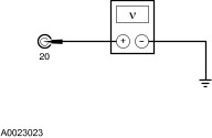
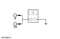
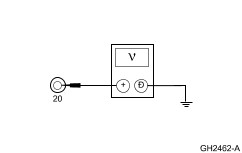
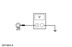
| - If the fault is not visually evident, connect the scan tool to the data link connector (DLC) located beneath the instrument panel and select the vehicle to be tested from the scan tool menu. If the scan tool does not communicate with the vehicle:
- check that the program card is correctly installed.
- check the connections to the vehicle.
- check the ignition switch position.
- If the scan tool still does not communicate with the vehicle, refer to the scan tool manual.
- Carry out the DATA LINK DIAGNOSTIC TEST. If the scan tool responds with:
- NO RESP/NOT EQUIP for anti-lock brake control module, go to Pinpoint Test A.
- SYSTEM PASSED, retrieve and record the continuous diagnostic trouble codes (DTCs), erase the continuous DTCs and carry out self-test diagnostics for the anti-lock brake control module.
- If the DTCs retrieved are related to the concern, go to Anti-Lock Brake Control Module Diagnostic Trouble Code (DTC) Index to continue diagnostics.
- If no DTCs related to the concern are retrieved, proceed to Symptom Chart.
Warning Lamp Indicators The anti-lock brake system uses the yellow ABS warning indicator to alert the driver of malfunctions in the ABS. The yellow ABS warning indicator will come on for numerous reasons. It warns the driver that the ABS has been deactivated due to a symptom that exists in the ABS. Normal power assist braking remains, but wheels can lock during a panic stop while the yellow ABS warning indicator is illuminated. The anti-lock brake system alerts the driver of an EBD fault by illuminating the red brake warning indicator. The diagnostic procedures must be followed step-by-step in order to correct the condition. Anti-Lock Brake Control Module Diagnostic Trouble Code (DTC) Index | DTC | Description | Action | | B1342 | Anti-Lock Brake Control Module Failure | INSTALL a new anti-lock brake control module. REFER to Module—Anti-Lock Brake Control REPEAT the self-test. | | B1676 | Battery Voltage Out Of Range | GO to Pinpoint Test B. | | C1095 | Hydraulic Pump Motor Circuit Failure | GO to Pinpoint Test E. | | C1145 | RF Anti-Lock Brake Sensor Circuit Failure (Static) | GO to Pinpoint Test C. | | C1155 | LF Anti-Lock Brake Sensor Circuit Failure (Static) | GO to Pinpoint Test C. | | C1165 | RR Anti-Lock Brake Sensor Circuit Failure | GO to Pinpoint Test C. | | C1175 | LR Anti-Lock Brake Sensor Circuit Failure | GO to Pinpoint Test C. | | C1233 | LF Anti-Lock Brake Sensor Output Failure | GO to Pinpoint Test D. | | C1234 | RF Anti-Lock Brake Sensor Output Failure | GO to Pinpoint Test D. | | C1235 | RR Anti-Lock Brake Sensor Output Failure | GO to Pinpoint Test D. | | C1236 | LR Anti-Lock Brake Sensor Output Failure | GO to Pinpoint Test D. | Anti-Lock Brake Control Module Parameter Identification (PID) Index | PID | Description | Expected Values | | CCNTABS | Number of Continuous DTCs on ABS | One count per bit | | BOOABS | Brake Pedal Position (BPP) Switch Input | ON, OFF | | ABSRLO | LR ABS Outlet Valve | ON, OFF | | ABSRRO | RR ABS Outlet Valve | ON, OFF | | ABSLFO | LF ABS Outlet Valve | ON, OFF | | ABSRFO | RF ABS Outlet Valve | ON, OFF | | ABSRLI | RL ABS Inlet Valve | ON, OFF | | ABSRRI | RR ABS Inlet Valve | ON, OFF | | ABSLFI | LF ABS Inlet Valve | ON, OFF | | ABSRFI | RF ABS Inlet Valve | ON, OFF | | LFWSPD | LF Wheel Speed | 0-255 KPH | | RFWSPD | RF Wheel Speed | 0-255 KPH | | LRWSPD | LR Wheel Speed | 0-255 KPH | | RRWSPD | RR Wheel Speed | 0-255 KPH | Anti-Lock Brake Control Module Active Command Index | Active Command | Display | Action | | ABS OUTPUT CONTROL | PMPMOTOR | ON, OFF | | | LFINLET | ON, OFF | | | RFINLET | ON, OFF | | | RRINLET | ON, OFF | | | RRINLET | ON, OFF | | | LROUTLET | ON, OFF | | | RROUTLET | ON, OFF | | | LFOUTLET | ON, OFF | | | RFOUTLET | ON, OFF | Symptom Chart NOTE:Refer to Wiring Diagrams for connector numbers stated in the Pinpoint Tests. Symptom Chart | Symptom | Possible Sources | Action | | No communication with the module — anti-lock brake control module | * CJB Fuse 15 (5A). * Circuitry. * Anti-lock brake control module. | * GO to Pinpoint Test A. | | Loss of sensor signal during vehicle deceleration or sensor signal drops out at low speed | * Anti-lock brake sensor indicator. * Sensor output is weak. * Air gap. | * GO to Pinpoint Test D. | | Unwarranted ABS activity | * Circuitry. * Anti-lock brake sensor. | * GO to Pinpoint Test D. | | Maladjusted rear brakes or "grabby" brake shoe or pad linings | * Rear brake adjustment. * Linings. | * | | Base brake mechanical concern for wheels lockup | * Rear brake shoe linings. * Wheel cylinder. * Rear brakes. | * | | * Parking brake. | * | | * Rear axle seal. | * | | Base brake hydraulic concern (soft pedal) | * Brake line or hose, fitting, master cylinder, wheel cylinder or caliper. * Air in brake system. | * | | Base brake mechanical concern (hard pedal) | * Vacuum boost. * Wheel cylinder or caliper. * Brake line or hose. | * | | Base brake hydraulic concern during medium/hard brake application | * Brake line or hose, fitting, master cylinder, wheel cylinder or caliper. * Air in brake system. | * | | Base brake mechanical concern during medium/hard brake application | * Vacuum boost. * Wheel cylinder or caliper. * Brake line or hose. * Brake shoe or pad linings. | * | | Base brake mechanical concern for vehicle pulls | * Rear brake. * Caliper. * Brake pad or shoe wear. | * | | Base brake hydraulic concern for vehicle pulls | * Brake line or hose. | * | | One wheel locks up; no DTCs recorded | * Base brake. | * | | * Dump valve. * ISO valve. | * | | The ABS warning indicator does not self check | * Bulb. * Circuitry. * Instrument cluster. * Anti-lock brake control module. | * GO to Pinpoint Test F. | | Soft or excessive brake pedal | * Brake line or hose, fitting, master cylinder, wheel cylinder, wheel cylinder or caliper. * Air in brake system. * HCU. | * | | ABS warning indicator always on, no DTC | * Circuitry. * Module. | * GO to Pinpoint Test G. | Pinpoint Tests | PINPOINT TEST A : NO COMMUNICATION WITH THE MODULE — ANTI-LOCK BRAKE CONTROL MODULE | | TEST CONDITIONS | DETAILS/RESULTS/ACTIONS | | A1: CHECK CIRCUIT 677 (LB) | | | 1 Ignition switch in position 0. | | | 2 Disconnect Anti-Lock Brake Control Module C155. | | | 3 Connect EEC-IV 60-Pin Breakout Box. | | | 4 Ignition switch in position II. | | | 5 Measure the voltage between EEC-IV 60-Pin Breakout Box pin and ground as follows: | EEC-IV 60-Pin Breakout Box Pin | Circuit | | 20 | 677 (LB) | | | | Is the voltage greater than 10 volts? Yes No REPAIR the circuit(s) in question. TEST the system for normal operation. | | A2: CHECK CIRCUIT 57 (BK) FOR AN OPEN | | | 1 Ignition switch in position 0. | | | 2 Measure the resistance between EEC-IV 60-Pin Breakout Box pin 8, circuit 57 (BK) and ground; and between EEC-IV 60-Pin Breakout Box pin 24, circuit 57 (BK) and ground. | | | Are the resistances less than 5 ohms? Yes No REPAIR the circuit. CLEAR the DTCs. REPEAT the self-test. | | PINPOINT TEST B : DTC B1676 — BATTERY VOLTAGE OUT OF RANGE | NOTE:DTC B1676 is generated when the anti-lock brake control module detects system voltage is less than 9 volts or greater than 19 volts for more than 8 seconds. | | TEST CONDITIONS | DETAILS/RESULTS/ACTIONS | | B1: CHECK BLOWN FUSE | | | 1 Check the blown fuse. | | | Is the fuse OK? Yes No INSTALL the fuse. | | B2: CHECK RECENT VEHICLE HISTORY | | | 1 Check recent vehicle history. | | | Has the vehicle been jump-started by a tow truck within the past two weeks? Yes The system is OK. CLEAR the DTCs. REPEAT the self-test. No | | B3: CHECK THE BATTERY VOLTAGE | | | 1 Measure the voltage between the positive and negative battery posts. | | | Is the voltage between 9 and 19 volts? Yes No | | B4: CHECK THE CHARGING SYSTEM | | | 1 Ignition switch in position III. | | | 2 With the engine running at 2,000 rpm, measure the voltage between the positive and negative battery posts. | | | Is the voltage between 9 and 19 volts? Yes No | | B5: CHECK CIRCUIT 677 (LB) FOR CORRECT VOLTAGE | | | 1 Ignition switch in position 0. | | | 2 Disconnect Anti-Lock Brake Control Module C155. | | | 3 Connect EEC-IV 60-Pin Breakout Box. | | | 4 Ignition switch in position II. | | | 5 Measure the voltage between EEC-IV 60-Pin Breakout Box pin 20, circuit 677 (LB) and ground. | | | Is the voltage greater than 10 volts? Yes No REPAIR the circuit. CLEAR the DTCs. REPEAT the self-test. | | B6: CHECK CIRCUIT 483 (RD) FOR CORRECT VOLTAGE | | | 1 Ignition switch in position 0. | | | 2 Measure the voltage between EEC-IV 60-Pin Breakout Box pin 25, circuit 483 (RD) and ground. | | | Is the voltage greater than 10 volts? Yes No REPAIR the circuit. CLEAR the DTCs. REPEAT the self-test. | | B7: CHECK CIRCUIT 534 (YE/LG) FOR CORRECT VOLTAGE | | | 1 Measure the voltage between EEC-IV 60-Pin Breakout Box pin 9, circuit 534 (YE/LG) and ground. | | | Is the voltage greater than 10 volts? Yes No REPAIR the circuit. CLEAR the DTCs. REPEAT the self-test. | | B8: CHECK CIRCUIT 57 (BK) FOR AN OPEN | | | 1 Measure the resistance between EEC-IV 60-Pin Breakout Box pin 8, circuit 57 (BK) and ground; and between EEC-IV 60-Pin Breakout Box pin 24, circuit 57 (BK) and ground. | | | Are the resistances less than 5 ohms? Yes No REPAIR the circuit. CLEAR the DTCs. | | PINPOINT TEST C : DTC C1145 (RF), DTC C1155 (LF), DTC C1165 (RR) AND DTC C1175 (LR) — ANTI-LOCK BRAKE SENSOR INPUT CIRCUIT FAILURE | | TEST CONDITIONS | DETAILS/RESULTS/ACTIONS | | C1: CHECK FOR SHORT TO POWER | | | 1 Ignition switch in position 0. | | | 2 Disconnect Anti-Lock Brake Control Module C155. | | | 3 Connect the EEC-IV 60-Pin Breakout Box. | | | 4 Ignition switch in position II. | | | 5 Measure the voltage between EEC-IV 60-Pin Breakout Box pins and ground as follows: | DTC | Breakout Box Pin | Breakout Box Pin | | C1145 (RF) | 4 (circuit 514 [YE/RD]) | 3 (circuit 516 [YE/BK]) | | C1155 (LF) | 18 (circuit 521 [TN/OG]) | 17 (circuit 522 [TN/BK]) | | C1165 (RR) | 6 (circuit 523 [RD/PK]) | 7 (circuit 524 [PK/BK]) | | C1175 (LR) | 22 (circuit 518 [LG/RD]) | 21 (circuit 519 [LG/BK]) | | | | Is voltage present? Yes REPAIR the suspect anti-lock brake sensor circuit(s). CLEAR the DTCs. TEST the system for normal operation. No | | C2: CHECK FOR SHORT TO GROUND | | | 1 Ignition switch in position 0. | | | 2 Measure the resistance between EEC-IV 60-Pin Breakout Box pins and ground as follows: | DTC | EEC-IV 60-Pin Breakout Box Pin | EEC-IV 60-Pin Breakout Box Pin | | C1145 (RF) | 4 (circuit 514 [YE/RD]) | 3 (circuit 516 [YE/BK]) | | C1155 (LF) | 18 (circuit 521 [TN/OG]) | 17 (circuit 522 [TN/BK]) | | C1165 (RR) | 6 (circuit 523 [RD/PK]) | 7 (circuit 524 [PK/BK]) | | C1175 (LR) | 22 (circuit 518 [LG/RD]) | 21 (circuit 519 [LG/BK]) | | | | Are the resistances greater than 10,000 ohms? Yes No REPAIR the circuit in question. CLEAR the DTCs. TEST the system for normal operation. | | C3: CHECK FOR AN OPEN | | | 1 Ignition switch in position 0. | | | 2 Disconnect Suspect Anti-Lock Brake Sensor Connector. | | | 3 Measure the resistance between EEC-IV 60-Pin Breakout Box pins and anti-lock brake sensor connector as follows: | DTC | EEC-IV 60-Pin Breakout Box Pin | Anti-Lock Brake Sensor Connector | | C1145 (RF) | 4 (circuit 514 [YE/RD]) | C160 (circuit 514 [YE/RD]) | | C1145 (RF) | 3 (circuit 516 [YE/BK]) | C160 (circuit 516 [YE/BK]) | | C1155 (LF) | 18 (circuit 521 [TN/OG]) | C150 (circuit 521 [TN/OG]) | | C1155 (LF) | 17 (circuit 522 [TN/BK]) | C150 (circuit 522 [TN/BK]) | | C1165 (RR) | 6 (circuit 523 [RD/PK]) | C426 (circuit 523 [RD/PK]) | | C1165 (LR) | 7 (circuit 524 [PK/BK]) | C426 (circuit 524 [PK/BK]) | | C1175 (LR) | 22 (circuit 518 [LG/RD]) | C440 (circuit 518 [LG/RD]) | | C1175 (LR) | 21 (circuit 519 [LG/BK]) | C440 (circuit 519 [LG/BK]) | | | | Are the resistances less than 5 ohms? Yes RECONNECT the anti-lock brake control module. GO to C4. . No REPAIR the circuit in question. CLEAR the DTCs. TEST the system for normal operation. | | C4: CHECK THE ANTI-LOCK BRAKE CONTROL MODULE OUTPUT | | | 1 Connect Anti-Lock Brake Control Module C155. | | | 2 Measure the voltage between suspect anti-lock brake sensor as follows: | DTC | Suspect Anti-Lock Brake Sensor Circuit | Suspect Anti-Lock Brake Sensor Circuit | | C1145 (RF) | 514 (YE/RD) | 516 (YE/BK) | | C1155 (LF) | 521 (TN/OG) | 522 (TN/BK) | | C1165 (RR) | 523 (RD/PK) | 524 (PK/BK) | | C1175 (LR) | 518 (LG/RD) | 519 (LG/BK) | | | | Is the voltage greater than 9 volts? Yes INSTALL a new anti-lock brake sensor. REFER to Sensor—Front or Sensor—Rear CLEAR the DTCs. TEST the system for normal operation. No | | PINPOINT TEST D : DTCS C1233, C1234, C1235 AND C1236 — ANTI-LOCK BRAKE SENSOR OUTPUT FAILURE | NOTE:Any time an anti-lock brake sensor is removed, thoroughly clean the mounting surfaces. On front anti-lock brake sensors, apply High-Temperature 4x4 Front Axle and Wheel Bearing Grease. | | TEST CONDITIONS | DETAILS/RESULTS/ACTIONS | | D1: CHECK FOR DTCS | | | 1 Ignition switch in position II. | | | 2 Connect the diagnostic tool. | | | 3 Retrieve DTCs. | | | Is DTC C1145, C1155, C1165 or C1175 present? Yes No | | D2: CHECK THE ANTI-LOCK BRAKE SENSOR PIDS | | | 1 Ignition switch in position II. | | | 2 Enter the following diagnostic mode: . 3 Monitor the anti-lock brake control module PIDS LFWSPD, RFWSPD, LRWSPD and RRWSP while driving the vehicle at a constant speed. | | | Are the anti-lock brake sensor PIDS consistent? Yes CLEAR the DTCs. DRIVE the vehicle. RETRIEVE DTCs. If DTC C1233, C1234, C1235 or C1236 is present, INSTALL a new anti-lock brake control module. REFER to Module—Anti-Lock Brake Control REPEAT the self-test. No | | D3: CHECK FOR ANTI-LOCK BRAKE SENSOR DAMAGE AND LOOSENESS | NOTE:Any time an anti-lock brake sensor is removed, thoroughly clean the mounting surfaces. On front anti-lock brake sensors, apply High-Temperature 4x4 Front Axle and Wheel Bearing Grease. | | | 1 Ignition switch in position 0. | | | 2 | | | CAUTION:Examine the anti-lock brake sensor wire carefully with good light. Failure to verify damage in the anti-lock brake sensor wire can lead to unnecessary installation of a new component. 3 Inspect the anti-lock brake sensor mounting for looseness. If the anti-lock brake sensor is suspected, inspect the sensor for corrosion on the rear axle housing boss, or on the front anti-lock brake mounting flange. Clean as necessary. | | | Is the anti-lock brake sensor OK? Yes No If the anti-lock brake sensor mounting is loose or corroded, REMOVE the anti-lock brake sensor, plug the opening, and thoroughly clean the mounting surfaces. On the front anti-lock brake sensors, APPLY High Temperature 4x4 Front Axle and Wheel Bearing Grease E8TZ-19590-A or equivalent meeting Ford Specification ESA-M1C198-A. REPEAT the self-test.If the anti-lock brake sensor is damaged, INSTALL a new anti-lock brake sensor.For the front anti-lock brake sensor, REFER to Sensor Indicator—Front CLEAR the DTCs. REPEAT the self-test.For the rear anti-lock brake sensor, REFER to Sensor—Rear CLEAR the DTCs. REPEAT the self-test. | | D4: CHECK FOR ANTI-LOCK BRAKE SENSOR INDICATOR DAMAGE | NOTE:Any time an anti-lock brake sensor is removed, thoroughly clean the mounting surfaces. On front anti-lock brake sensors, apply High Temperature 4x4 Front Axle and Wheel Bearing Grease. | | | 1 Remove the anti-lock brake sensor. | | | CAUTION:Examine the anti-lock brake sensor indicator carefully with good light. Failure to verify damage in the anti-lock brake sensor indicator can lead to unnecessary installation of a new component. 2 Inspect the anti-lock brake sensor indicator for damaged or missing teeth. Rotate the wheel to verify that no teeth are missing. | | | Is the anti-lock brake sensor indicator OK? Yes No INSTALL a new anti-lock brake sensor indicator.For the front anti-lock brake sensor indicator, REFER to Sensor Indicator—Front CLEAR the DTCs. REPEAT the self-test.For the rear anti-lock brake sensor indicator, REFER to Sensor Indicator—Rear CLEAR the DTCs. REPEAT the self-test. | | D5: CHECK THE ANTI-LOCK BRAKE CONTROL MODULE OUTPUT | | | 1 Ignition switch in position II. | | | 2 Measure the voltage between the suspect anti-lock brake sensor as follows: | DTC | Suspect Anti-Lock Brake Sensor Circuit | Suspect Anti-Lock Brake Sensor Circuit | | C1234 (RF) | 514 (YE/RD) | 516 (YE/BK) | | C1233 (LF) | 521 (TN/OG) | 522 (TN/BK) | | C1235 (RR) | 523 (RD/PK) | 524 (PK/BK) | | C1236 (LR) | 518 (LG/RD) | 519 (LG/BK) | | | | Is the voltage greater than 9 volts? Yes INSTALL a new anti-lock brake sensor. REFER to Sensor—Front or Sensor—Rear CLEAR the DTCs. TEST the system for normal operation. No | | PINPOINT TEST E : DTC C1095 — HYDRAULIC PUMP MOTOR CIRCUIT FAILURE | | TEST CONDITIONS | DETAILS/RESULTS/ACTIONS | | E1: CHECK THE ABS PUMP MOTOR | | | 1 Ignition switch in position II. | | | Is the pump motor on constantly? Yes No | | E2: CHECK THE PUMP MOTOR OPERATION | | | 1 Connect the diagnostic tool. | | | 2 Ignition switch in position II. | | | 3 Enter the following diagnostic mode: . 4 Trigger the anti-lock brake control module active command PMP MOTOR ON. | | | Does the pump motor operate? Yes CLEAR the DTC. CHECK the yellow ABS warning indicator while driving the vehicle above 32 km/h (20 mph) and no brakes applied until the vehicle exceeds 32 km/h (20 mph). If the yellow ABS warning indicator illuminates, INSTALL a new anti-lock brake control module. REFER to Module—Anti-Lock Brake Control CLEAR the DTCs. REPEAT the self-test. If the yellow ABS warning indicator does not illuminate, CLEAR the DTCs. REPEAT the self-test. No | | E3: CHECK THE PUMP MOTOR | | | 1 Ignition switch in position 0. | | | 2 Disconnect Pump Motor Connector. | | | 3 Connect a fused 50A jumper wire between the positive battery terminal and red ABS pump motor terminal. Connect a jumper wire between the negative battery terminal and brown ABS pump motor terminal. | | | Is the ABS pump motor running? Yes No | | E4: CHECK CIRCUIT 534 (YE/LG) | | | 1 Ignition switch in position 0. | | | 2 Disconnect Anti-Lock Brake Control Module C155. | | | 3 Connect EEC-IV 60-Pin Breakout Box. | | | 4 Ignition switch in position II. | | | 5 Measure the voltage between EEC-IV 60-Pin Breakout Box pin 9, circuit 534 (YE/LG) and ground. | | | Is the voltage greater than 10 volts? Yes No REPAIR the circuit(s) in question. CLEAR the DTCs. REPEAT the self-test. | | E5: CHECK CIRCUIT 57 (BK) FOR AN OPEN | | | 1 Ignition switch in position 0. | | | 2 Measure the resistance between EEC-IV 60-Pin Breakout Box pin 8, circuit 57 (BK) and ground; and between EEC-IV 60-Pin Breakout Box pin 24, circuit 57 (BK), and ground. | | | Are the resistances less than 5 ohms? Yes No REPAIR the circuit. CLEAR the DTCs. REPEAT the self-test. | | PINPOINT TEST F : THE YELLOW ABS WARNING INDICATOR DOES NOT SELF-CHECK | | TEST CONDITIONS | DETAILS/RESULTS/ACTIONS | | F1: CHECK THE ANTI-LOCK BRAKE CONTROL MODULE | | | 1 Ignition switch in position 0. | | | 2 Disconnect Anti-Lock Brake Control Module C155. | | | 3 Connect EEC-IV 60-Pin Breakout Box. | | | 4 Ignition switch in position II. | | | 5 Connect a fused (10A) jumper between EEC-IV 60-Pin Breakout Box pin 16, circuit 603 (DG) and ground. | | | Does the yellow ABS warning indicator illuminate? Yes VERIFY that all repair procedures have been carried out and DTCs have been repaired. INSTALL a new anti-lock brake control module. REFER to Module—Anti-Lock Brake Control REPEAT the self-test. No | | F2: CHECK CIRCUIT 398 (BK/YE) FOR AN OPEN | | | 1 Disconnect Instrument Cluster C2206. | | | 2 Measure the resistance between EEC-IV 60-Pin Breakout Box pin 16, circuit 398 (BK/YE) and instrument cluster C288 pin 7, circuit 603 (DG). | | | Is the resistance less than 5 ohms? Yes INSTALL a new instrument cluster printed circuit. REFER to Section 413-01 Instrument Cluster. TEST the system for normal operation. No REPAIR the circuit. TEST the system for normal operation. | | PINPOINT TEST G : ABS WARNING INDICATOR ALWAYS ON, NO DTCS | | TEST CONDITIONS | DETAILS/RESULTS/ACTIONS | | G1: CHECK THE MODULE | | | 1 Disconnect Anti-Lock Brake Control Module C155. | | | 2 Ignition switch in position II. | | | Does the ABS warning indicator illuminate? Yes No | | G2: CHECK CIRCUIT 398 (BK/YE) FOR SHORT TO GROUND | | | 1 Ignition switch in position 0. | | | 2 At the ABS control module connector, press the shorting bar. | | | Is the ABS warning indicator off? Yes RESEAT the connector. If warning indicator remains on, INSTALL a new ABS control module. No REPAIR circuit 398 (BK/YE). REPEAT the self-test. | |