| Removal and Installation Special Tool(s) | | Lever, Wheel Knuckle 204-159 (14-039) | | | Installer, Halfshaft 204-161 (14-041) | | | Separator, Ball Joint 211-020 (13-006) | General Equipment Removal All Vehicles | | -
CAUTION:Use an Allen key to prevent the piston rod from rotating. Loosen the strut and spring assembly top mount by five turns. | | | -
CAUTION:Use a socket to loosen the wheel hub retaining nut to prevent damage. Loosen the wheel hub retaining nut. | | | -
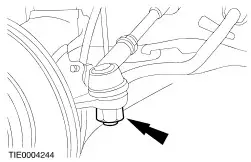
CAUTION:Leave the tie-rod end retaining nut in place to protect the ball joint stud. Loosen the tie-rod end retaining nut. | | | -
CAUTION:Protect the ball joint seal using a soft cloth to prevent damage. Using the special tool, release the tie-rod end from the wheel knuckle. - Release the tie-rod end.
- Remove and discard the tie-rod end retaining nut.
| | | -
CAUTION:Suspend the brake caliper and anchor plate assembly out of the way to prevent damage to brake hose. Detach the brake caliper and anchor plate assembly. | Vehicles with anti-lock brakes | | -
Detach the front wheel speed sensor from the wheel knuckle. | All Vehicles | | -
Remove the brake disc. - Remove the retainers (if equipped).
| | | -
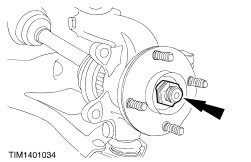
CAUTION:Use a socket to remove the wheel hub retaining nut to prevent damage. Remove the wheel hub retaining nut. | | | -
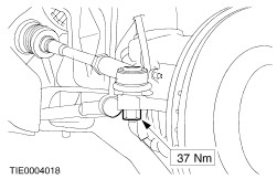
CAUTION:Protect the ball joint seal using a soft cloth to prevent damage. Detach the lower arm from the wheel knuckle. | | | -
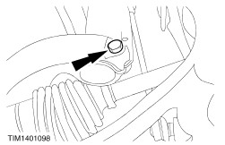
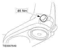
Remove the wheel knuckle to strut and spring assembly pinch bolt. | | | -
CAUTION:The inner joint must not be bent more than 18 degrees, the outer joint must not be bent more than 45 degrees. Using a suitable two leg puller, detach the wheel hub from the halfshaft. | | | -
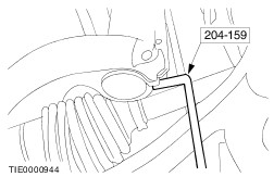
Using the special tool, remove the wheel knuckle. | Installation All Vehicles | | -
Install the wheel knuckle. | | | -
CAUTION:Make sure the halfshaft is completely installed into the wheel hub. Using the special tool, install the halfshaft into the wheel hub. | | | -
Install the lower arm ball joint to the wheel knuckle. | | | -
Attach the brake caliper and anchor plate assembly to the wheel knuckle. | Vehicles with anti-lock brakes | | -
Attach the front wheel speed sensor to the wheel knuckle. | All Vehicles | | -
WARNING:Install a new tie-rod retaining nut. Failure to follow this instruction may result in personal injury. Attach the tie-rod end retaining nut. - Install a new tie-rod end retaining nut.
| | | -
CAUTION:The hub retaining nut can be re-used four times, mark the hub retaining nut. With the aid of another technician, apply the brakes and pre load the wheel bearing. | | | -
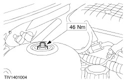
Tighten the wheel hub retaining nut. | | | -
CAUTION:Use an Allen key to prevent the piston rod from rotating. Tighten the strut and spring assembly top mount nut. | |