| Disassembly and Assembly Disassembly All vehicles | | -
Detach the driver air bag module. | | | -
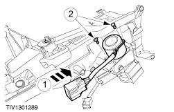
WARNING:To minimize the possibility of injury in the event of premature deployment, always carry a live air bag module with the bag and trim cover pointed away from the body. Failure to follow this instruction may result in personnel injury. WARNING:To minimize the possibility of premature deployment, live air bag modules must only be placed on work benches which have been ground bonded and with the trim cover facing up. Failure to follow these instructions may result in personal injury. Remove the driver air bag module. - Disconnect the driver air bag module electrical connector.
- Remove the driver air bag module.
| | | -
Disconnect the horn electrical connector. | | | -
Remove the steering wheel retaining bolt. | | | -
Remove the steering wheel. | | | -
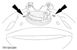
Remove the air bag sliding contact. - Release the air bag sliding contact retaining clips.
- Remove the air bag sliding contact.
| Vehicles with 2.5L (200PS) engine | | -
Remove the passive anti-theft system (PATS) transceiver | | | -
- Remove the steering lock shield.
| All vehicles | | -
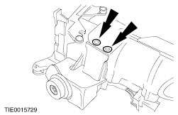
Remove the ignition switch. - Remove the ignition switch retaining screws.
- Disconnect the ignition switch electrical connector.
| | | -
Remove the PATS transceiver. | Vehicles with automatic transaxle | | -
Remove the key release actuator. | All vehicles | | -
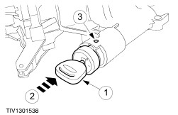
Remove the ignition switch lock barrel. - Turn the ignition switch to position I (accessory).
- Depress the ignition switch lock barrel retaining pin.
- Remove the ignition switch lock barrel.
| | | -
Remove the upper bearing retaining collar. | | | -
Disengage the column shaft from the upper bearing. | | | -
Remove the lower bearing cap. | | | -
Remove the column shaft and bearing assembly. | | | -
Using a suitable drift remove the upper bearing from inside the column tube. | | | -
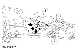
NOTE:Make sure all traces of thread locking compound are removed from the retaining bolt threads. Remove the steering column adjust lever assembly. - Remove the steering column adjust lever retaining nut.
- Remove the steering column adjust lever.
- Remove the cam.
- Remove the clamp assembly.
| | | -
NOTE:Make sure all traces of thread locking compound are removed from the retaining bolt threads. Remove the steering column mounting bracket. | | | -
Remove the steering column position springs. | Assembly All vehicles | | -
Install the steering column position springs. | | | -
NOTE:Apply thread locking compound to the retaining bolt threads. Install the column mounting bracket. | | | -
Install the steering column adjust lever. - Install the clamp assembly.
- Install the cam washer.
- Install the steering column adjust lever.
| | | -
CAUTION:Make sure the steering column adjust lever securely locks the steering column in position. Make sure this procedure is completed before the thread locking compound sets. Adjust the steering column lever. - Apply thread locking compound to the retaining bolt threads.
- Install and partially tighten the retaining nut.
- If the steering column adjust lever does not operate correctly, slacken or tighten the retaining nut until the correct adjustment is obtained.
| | | -
Using a suitable drift install a new upper bearing. | | | -
Install the steering column shaft assembly. | | | -
Install the lower bearing cap. | | | -
Install the upper bearing retaining collar. | | | -
Install the ignition switch lock barrel. - Make sure ignition switch lock barrel is in position I (accessory).
- Install the ignition switch lock barrel.
- Make sure the ignition switch lock barrel retaining pin is located correctly.
| Vehicles with automatic transaxle | | -
Install the key release actuator. | All vehicles | | -
Install the ignition switch assembly. - Connect the ignition switch electrical connector.
- Install the ignition switch retaining screws.
| | | -
Align the steering column shaft. - Remove the ignition key to lock into position.
| Vehicles with 2.5L (200PS) engine | | -
CAUTION:When installing the steering lock shield make sure that no cables are trapped or damaged. NOTE:The steering lock shield retaining bolts are designed to shear at the specified torque. NOTE:The steering lock shield bolts must be hand started before tightening with a power tool. Install the steering lock shield. | | | -
Install the PATS transceiver. | All vehicles | | -
WARNING:Make sure the air bag sliding contact is centralized before installing. Failure to follow this instruction may result in personal injury. WARNING:If there is any doubt about the centralization of the air bag sliding contact, the air bag sliding contact centralization procedure must be repeated. Failure to follow this instruction may result in personal injury. Centralize the air bag sliding contact. - Rotate the inner rotor against the outer rotor fully counter clockwise until tight.
- Then rotate the inner rotor clockwise approximately 2.75 turns until the alignment markings are aligned and the locking tab locates in the slot.
| | | -
Install the air bag sliding contact. | | | -
CAUTION:If there is any break between centralizing the air bag sliding contact and installing the steering wheel, or the vehicle left unattended by the technician, the centralizing procedure MUST be repeated. Install the steering wheel. | | | -
Connect the horn electrical connector. | | | -
Install the driver air bag module. - Connect the driver air bag module electrical connector.
| |