| In-vehicle Repair Special Tool(s) | | Universal flange holding wrench 15-030 A | | | Subframe locating pins 15-097A | | | Lifting bracket, engine 21-068A | | | Timing pin, crankshaft 21-104 | | | Timing tool, camshaft alignment 21-162B | | | Socket, cylinder head bolts 21-164 | | | Gauge, engine alignment 21-172 | | | Angle gauge, bolt tightening 21-540 | | | Timing pin, injection pump timing 23-019 | | | Socket, injectors 23-045 | Materials Name Specification Cable ties Coolant ESDM-97B49-A Engine oil SAE5W-30 WSS-M2C912–A1 Removal All Vehicles | | -
Standard preparatory measures - Make a note of the radio keycode.
- Make a note of the preset radio stations.
- Slacken the wheel nuts of the front right-hand wheel.
| | | -
Raise the vehicle. - Remove the front right-hand wheel.
| | | -
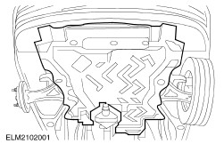
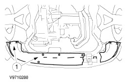
Remove the engine undershield (nine bolts). | | | -
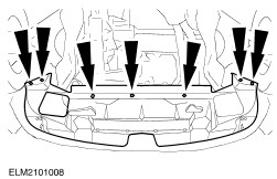
NOTE:After draining off the coolant, re-tighten the coolant drain plug to 23 Nm. Drain off the coolant. - Detach the lower radiator cover.
- Remove the drain plug.
| | | -
NOTE:The guide pins should be able to be inserted in the subframe and the body locating holes without strain, otherwise the subframe must be realigned. Check the position of the subframe. | | | -
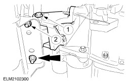
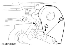
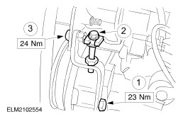
Remove the front engine roll restrictor. - Unscrew the center bolt.
- Detach the engine roll restrictor from the subframe.
| | | -
NOTE:The gauge must be able to be fitted without strain, otherwise the engine/transmission assembly must be realigned. Fit the gauge in the place of the engine roll restrictor. - Attach the gauge to the subframe.
- Screw in the center bolt.
| | | -
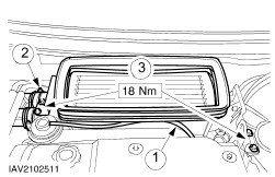
Detach the right-hand wheel arch cover. | | | -
Remove the air cleaner. - Pull out the plug of the mass air flow (MAF) sensor.
- Release the hose clip.
- Disconnect the low pressure hose.
- Remove the rubber retainer.
| | | -
NOTE:Close off the turbocharger opening using a clean, lint-free cloth. Remove the intercooler. - Undo the two bolts on each side.
- Disconnect the hose.
- Unclip the low pressure hose.
| | | -
Disconnect the plug from the thermostat housing. - Coolant temperature gauge sender unit
- Engine coolant temperature sensor (ECT sensor)
- Needle lift sensor
- Remove the nut from the glow plug wiring.
| | | -
Disconnect the coolant pipe from the coolant expansion tank and disconnect the fuel return pipe. | | | -
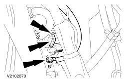
Pull out the plugs and disconnect the fuel pipes. - From the oil pressure switch.
- From the fuel heater.
- Disconnect the two plugs of the main engine wiring harness.
- Disconnect the fuel pipes at the fuel filter.
| | | -
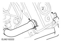
Disconnect the vacuum pipe and the oil return pipe from the vacuum pump. | | | -
Detach the thermostat housing. - Remove the oil dipstick tube.
- Detach the bracket for the glow plug wiring.
- Detach the thermostat housing from the cylinder head.
| | | -
Detach the PCV hoses. - To the cylinder block.
- To the turbocharger.
| | | -
NOTE:Close the injection pump, injection pipe and injector openings with caps. Disconnect the leak-off hoses and detach the injection pipes from the injection pump and injectors. | | | -
Remove the fuel filter (two bolts). - Detach the bracket for the charge air pipe.
| | | -
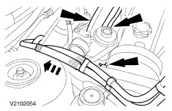
Disconnect the coolant hoses and the exhaust gas recirculation (EGR) hose. - Move the coolant hoses towards the hood.
| | | -
Disconnect the starter motor (two plugs, one nut). | | | -
Detach the exhaust manifold from the catalytic converter. | | | -
CAUTION:Insert the wooden block between the oil pan and the trolley jack. Position the trolley jack with the wooden block under the oil pan and raise so that the front engine mounting bracket is free from strain. | | | -
Remove the power steering pump belt cover. - Undo the two bolts.
- Undo the bolt of the power steering pump.
| | | -
Detach the drive belt tensioner from the power steering pump. - Release the bolt.
- Slacken the drive belt using the adjusting bolt.
- Detach the tensioner.
| | | -
Remove the drive belt and detach the power steering pump. - Tie up the power steering pump.
| | | -
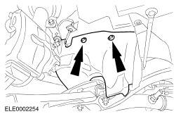
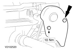
Detach the front engine mounting bracket. | | | -
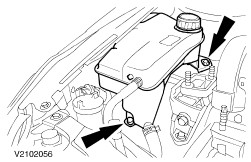
Detach the coolant expansion tank. | | | -
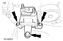
Remove the front engine mounting. | | | -
Undo the engine lifting eye bolts. | | | -
Detach the injection pump belt pulley and disconnect the coolant hose from the coolant pump. | Vehicles with air conditioning | | -
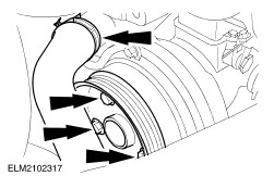
Remove the drive belt of the air conditioning compressor. - Release the tensioning bolt.
- Remove the drive belt.
| | | -
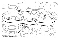
Remove the generator drive belt. - Release the bolt.
- Slacken the drive belt using the adjusting bolt and remove it.
| | | -
Disconnect the turbocharger oil return pipe. | | | -
Detach the lower timing belt cover. | | | -
Detach the upper timing belt cover. - Release the three clips and undo the single bolt.
| | | -
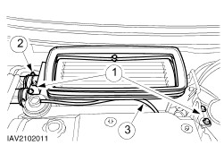
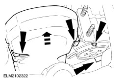
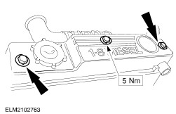
Detach the cylinder head cover. | | | -
Turn the crankshaft to TDC position. - Turn the crankshaft in the normal direction of rotation until the slot in the injection pump timing pulley is at 11 o'clock.
- Remove the blanking plug and screw in Special Tool .
- Carefully turn the crankshaft until it comes up against Special Tool .
| | | -
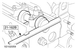
Insert the special tool in the camshaft. | | | -
Detach the camshaft timing belt. NOTE:Hold the camshaft timing pulley with Special Tool 15-030A. - Slacken the bolt of the camshaft timing pulley.
- Loosen the bolt of the adjusting cam and slacken the camshaft timing belt.
- Detach the camshaft timing belt tensioner.
| | | -
NOTE:Insert a screwdriver between the camshaft timing pulley and the rear timing belt cover. Remove the camshaft timing pulley. - Release the camshaft timing pulley from its conical seat by tapping with a soft metal drift.
| | | -
Remove the injectors. - Take out the heat shields.
| | | -
NOTE:Slackening sequence. Slacken the cylinder head bolts and remove them. | | | -
Attach the special tool to the engine lifting eyes and lift the cylinder head out of the vehicle. - Place the cylinder head down on a soft surface.
- Remove the cylinder head gasket.
| Installation All Vehicles | | -
Preparatory operations. - Clean the mating faces thoroughly.
- Put the new cylinder head gasket in place.
- Check that the guide sleeves are sitting correctly.
- Gasket thickness indicator
| | | -
NOTE:The pistons must not be at TDC. Do not damage the rear timing belt cover. Ensure that the adjusting tool is engaged in the camshaft groove. Using the special tool, position the cylinder head on the cylinder block. | | | -
CAUTION:Use new unoiled cylinder head bolts. The cylinder head bolts must not be retorqued. Tighten the cylinder head bolts in five stages. - Tighten the cylinder head bolts in two stages in the specified sequence using a socket.
| | | -
CAUTION:In the third stage, first slacken the cylinder head bolts then tighten to the required torque and by the required angle in accordance with the tightening sequence. Only then move onto the next bolt. CAUTION:The cylinder head bolts must not be retorqued. Wait three minutes and then tighten the cylinder head bolts. - Stage 3: Slacken bolt by 120 degrees.
- Stage 4: Tighten bolt to 70 Nm.
- Stage 5: Tighten bolt by 120 degrees.
| | | -
NOTE:Use new heat shields. Install the injectors. | | | -
CAUTION:The camshaft timing belt and injection pump timing belt must be renewed each time they are slackened. Retensioning is not permitted. CAUTION:The crankshaft must bear on the timing pin and the timing tool must be inserted in the camshaft. NOTE:The running direction is marked. NOTE:Only screw in the bolt - do not tighten it. NOTE:Make sure that the timing belt is lying centrally on all the timing pulleys. Fit the camshaft timing belt. - Fit the camshaft timing belt tensioner.
- Fit the adjusting cam.
- Fit the camshaft timing belt.
- Lubricate the bolt contact face with engine oil 5W-30.
- Bring the camshaft timing pulley with the fitted timing belt into position, screw in the bolt of the camshaft timing pulley as far as it will go and slacken it a quarter of a turn.
| | | -
Check the adjustment of the injection pump. - Insert Special Tool 23-019 in the injection pump timing pulley.
- If Special Tool 23-019 cannot be inserted, the injection pump must be realigned.
| | | -
Pretighten the camshaft timing belt. - Turn the adjusting cam clockwise to 9 o'clock and tighten the center bolt of the adjusting cam.
NOTE:Hold the camshaft timing pulley with Special Tool 15-030A. - Tighten the bolt of the camshaft timing pulley.
| | | -
CAUTION:Remove the special tools. Turn the crankshaft six turns in the normal direction of rotation. | | | -
Preparations for tensioning the timing belts. - Turn the crankshaft further in the engine's normal direction of rotation until the slot in the injection pump timing pulley is at 11 o'clock.
| | | -
NOTE:Hold the camshaft timing pulley. Loosen the bolt of the camshaft timing pulley and slacken the camshaft timing belt. | | | -
NOTE:Insert a screwdriver between the camshaft timing pulley and the rear timing belt cover. Release the camshaft timing pulley from its conical seat by tapping lightly with a soft metal drift. | | | -
NOTE:If necessary, turn the camshaft using water pump pliers until the timing tool can be inserted. Insert the timing tool in the camshaft groove. | | | -
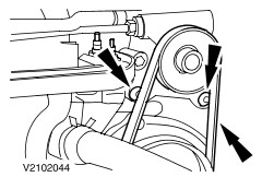
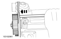
NOTE:Use a mirror to get a better view. Tension the camshaft timing belt. NOTE:Hold the bolt of the adjusting cam. - Tension the camshaft timing belt clockwise using the hexagon socket of the adjusting cam until the arrows on the camshaft timing belt tensioner meet.
NOTE:Tighten the bolt smoothly. - Tighten the bolt of the adjusting cam.
NOTE:Hold the camshaft timing pulley. NOTE:Tighten the bolt smoothly. NOTE:Tightening torque of the camshaft timing pulley bolt. - Tighten the bolt of the camshaft timing pulley.
| | | -
CAUTION:Remove the special tools. Turn the crankshaft four turns in the normal direction of rotation. | | | -
NOTE:If the special tools cannot be inserted, the adjustment must be repeated from step . Check the valve timings. - Turn the crankshaft further in the engine's normal direction of rotation until the slot in the injection pump timing pulley is at 11 o'clock.
- Special Tool 23-019 must be able to be inserted.
- Special Tool 21-162B must be able to be fitted in the camshaft groove.
- The arrows on the camshaft timing belt tensioner must not be offset by more than 3 mm.
- Remove the special tools and fit the blanking plug in the place of the timing pin.
| | | -
Check valve clearance and adjust if necessary. For additional information, refer to Valve Clearances - Adjust in this section. | | | -
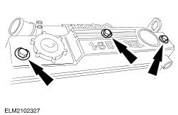
NOTE:Clean and inspect the gasket and renew it if necessary (it can be reused several times). Attach the cylinder head cover. - Before installing, lubricate with engine oil 5W-30.
| | | -
Attach the PCV hoses. - To the cylinder block.
- To the turbocharger.
| | | -
Fit the upper timing belt cover. - Bring the cover into position from above.
- Fit the three clips and tighten the bolt.
| | | -
Raise the vehicle. Connect the turbocharger oil return pipe. | | | -
Fit the lower timing belt cover. | | | -
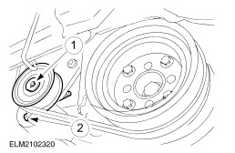
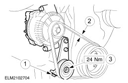
Fit the generator drive belt. - Fit the drive belt and tension it with the adjusting bolt.
- Check the drive belt tension:
- Secure the idler pulley.
| Vehicles with air conditioning | | -
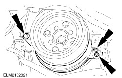
Fit the drive belt of the air conditioning compressor. - Tension it with the idler pulley.
- Check the drive belt tension:
| | | -
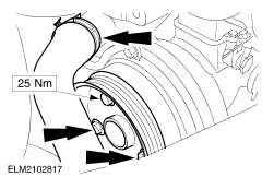
Lower the vehicle. NOTE:Fit the belt pulley and lower bolt at the same time. Fit the injection pump belt pulley and connect the coolant hose to the coolant pump. | | | -
Tighten the bolts of the engine lifting eye. | | | -
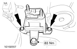
Fit the front engine mounting. | | | -
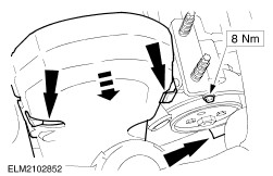
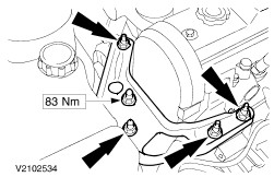
NOTE:Fit new nuts. Do not install the engine mounting bracket under stress. If necessary, lower the engine using the support bar until the bracket can be installed free from stress. Attach the front engine mounting bracket. | | | -
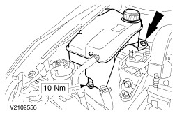
Fit the coolant expansion tank. | | | -
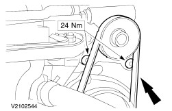
Fit the power steering pump and the drive belt. | | | -
Fit the power steering pump drive belt tensioner. - Attach the tensioner to the timing cover.
- Tension the drive belt using the adjusting bolt.
- Tighten the bolt.
| | | -
Fit the power steering pump cover. | | | -
Lower the engine using a trolley jack. | | | -
Attach the catalytic converter. | | | -
Connect the starter motor (two plugs and one nut). | | | -
Connect the coolant hoses and the EGR hose. | | | -
Fit the fuel filter (two bolts). - Attach the bracket for the charge air pipe.
| | | -
Fit the injection pipes to the injectors and injection pump and connect the leak-off hoses. | | | -
Attach the thermostat housing to the cylinder head. - Attach the thermostat housing.
- Fit the bracket for the glow plug wiring.
- Fit the oil dipstick tube.
| | | -
Connect the vacuum pipe and the oil return pipe to the vacuum pump. | | | -
Connect the plugs and the fuel pipes. - To the oil pressure switch.
- To the fuel heater.
- Connect the two main engine wiring harness plugs.
- Connect the fuel pipes to the fuel filter.
| | | -
Attach the coolant pipe to the coolant expansion tank and connect the fuel return pipe. | | | -
Connect the plugs to the thermostat housing. - Coolant temperature gauge sender unit
- ECT sensor.
- Needle lift sensor
- Fit the glow plug power supply.
| | | -
Install the intercooler. - Clip the low pressure hose in place.
- Connect the hose.
- Screw in the two bolts on each side.
| | | -
Fit the air cleaner. - Fit the rubber retainer.
- Push on the low pressure hose.
- Push on the intake hose and do up the hose clip.
- Connect the plug to the MAF sensor.
| | | -
Attach the front engine roll restrictor. - Fit the bolts in position.
- Tighten the two bolts.
- Tighten the center bolt.
| | | -
Fit the right-hand wheel arch cover. | | | -
Fit the lower radiator shroud. - Hook the radiator shroud into the radiator crossmember.
- Screw in the bolts.
| | | -
Standard finishing operations. - Check the routing of the wiring and hoses and secure them with cable ties where necessary.
- Connect the battery negative lead.
- Reprogram the preset radio stations.
- Carry out a road test to enable the PCM to collect data.
- Check the fluid levels again and correct as necessary.
| | | -
Raise the vehicle. - Check the engine for leaks (visual inspection).
| | | -
Attach the engine undershield. | |