| Removal Special Tool(s) | | Separator, Ball Joint 211-020 (13-006) | | | Lifting Bracket, Engine 303-122 (21-068A) | | | Remover, Halfshaft 308-192 (16-057) | General Equipment Jib crane Assembly plugs Assembly table GV2166 Removal | | -
Standard preparatory measures - Make a note of the radio keycode.
- Make a note of the pre-set radio stations.
- Open the coolant expansion tank.
| | | -
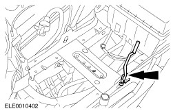
Lock the gearshift mechanism. - Remove the boot from the gear lever.
- Put the transmission into neutral.
- Pull the reverse gear lock up and put the adjusting tool in place.
| | | -
Make help tool to fix hood in open position. | | | -
Open the hood and attach the help tool to the hood. | | | -
Undo the left and right-hand suspension strut nuts five turns (right-hand side shown). | | | -
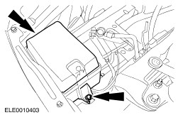
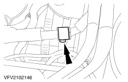
Remove the fuse box. - Pull out from battery tray.
| | | -
Unclip cable on battery tray. | | | -
Remove the engine undershield (nine bolts). | | | -
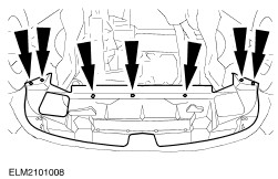
Detach the lower radiator cover. - Unscrew the bolts.
- Unhook the radiator cover from the radiator crossmember.
| | | -
CAUTION:Risk of scalding when engine is at operating temperature. Drain the coolant. - Detach the coolant hose from the radiator.
| | | -
NOTE:Close off the opening to the turbocharger using a lint-free cloth. Detach the intercooler. - Take out the two bolts on each side.
- Detach the hose.
- Unclip the low pressure hose.
| | | -
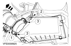
Remove the air cleaner. - Pull off the connector on the mass air flow (MAF) sensor.
- Disconnect the low pressure hose.
- Undo the retaining clips.
| | | -
Detach coolant hoses on coolant expansion tank. | | | -
Remove coolant expansion tank. | | | -
WARNING:Risk of scalding if the engine is hot. Drain the coolant from the lower coolant hose connection pipe and detach the lower coolant hose from the connection pipe. | | | -
Detach coolant hose from coolant pump. | | | -
CAUTION:Over bending of the flexible pipe may cause damage resulting in failure. Support the flexible pipe with a support wrap or suitable splint assembly. | | | -
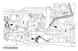
Separate fuel lines. - Separate fuel line.
- Detach vacuum line.
- Detach coolant hose.
| | | -
Detach accelerator cable and cold starting system cable. - Pull off accelerator cable.
- Pull off the clip.
- Pull the accelerator pedal out of the bracket and lay it to one side.
- Detach the cold starting system cable.
| | | -
Pull off the exhaust gas recirculation (EGR) valve. | | | -
Detach the glow plug power supply. | | | -
Separate the main engine wiring harness connector. - Undo the cable ties and lay the engine main wiring harness to one side.
- Unclip speedometer lever (VSS) and clutch slave cylinder hydraulic line from selector cable bracket.
| | | -
Detach ground lead on transmission. | | | -
Drain power steering reservoir. | | | -
Detach the pipes from the power steering pump. - Low pressure hose
- High pressure pipe
| | | -
Detach the power steering pipe bracket from the generator. | | | -
Detach the heater coolant hoses. | | | -
Detach the catalytic converter from the exhaust manifold. | | | -
Remove the catalytic converter. | | | -
Remove the catalytic converter. | | | -
Disconnect the starter motor. | | | -
Detach front right wheel housing covers. | | | -
Detach rear left wheel housing cover (right-hand side shown). | | | -
Remove the air conditioning compressor drive belt. - Release the tensioning bolt.
- Remove the drive belt.
| | | -
Remove the crankshaft pulley/vibration damper. | | | -
Detach the air conditioning compressor from the bracket. - Pull off the electromagnetic clutch connector.
- Unscrew the bolts.
| | | -
Remove the air-conditioning compressor bracket. | | | -
Detach the coolant line bracket. | | | -
Remove the right-hand transverse link from the spindle carrier (left-hand side shown). | | | -
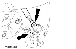
Detach the left-hand transverse link. - Detach the stabiliser bar connecting link.
- Detach the track rod end.
- Remove the transverse link from the spindle carrier.
| | | -
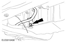
NOTE:Lower nut with coolant line bracket. Detach the front driveshaft center bearing from the bracket, pull out the right-hand front driveshaft from the transmission and tie it up. - Refit the coolant line bracket loose on the sump.
| | | -
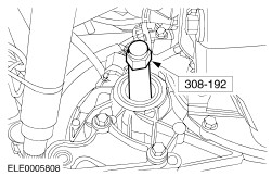
CAUTION:The inner tripod joint must not be bent more than 18 degrees, the outer joint not more than 45 degrees. Remove the left-hand front driveshaft. - Free the front driveshaft from its seat.
- Pull the front driveshaft out of the transmission and tie it up.
- Close off both holes in the transmission using assembly plugs.
| | | -
Remove the left-hand engine roll restrictor. - Unscrew and remove the centre bolt from the left-hand engine roll restrictor.
| | | -
Detach the left-hand engine roll restrictor bracket from the transmission. | | | -
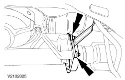
Remove the right-hand engine roll restrictor. - Unscrew the center bolt.
- Remove the bolts.
| | | -
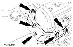
Detach the right-hand engine roll restrictor bracket from the transmission (three bolts). | | | -
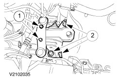
Detach the gearshift cables from the transmission. - Unclip the shift and selector cable.
- Remove the nuts.
- Remove the bracket and lay to one side.
| | | -
NOTE:Close off the openings using plugs. Detach the hydraulic pipe from the clutch slave cylinder. - Pull out the safety clip and pull off the hydraulic pipe.
- Unclip the hydraulic pipe upwards out of the bracket.
| | | -
Attach engine and transmission to jib crane using special tool. | | | -
Remove the rear engine mounting. - Remove the air cleaner bracket.
- Remove the rear engine mounting.
| | | -
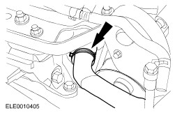
Loosen the front engine mounting. | | | -
Remove the engine and transmission by lifting upwards. | | | -
Lift the engine and transmission onto assembly table and secure using retaining strap. | | | -
Separate engine from transmission. | | |