| Removal and Installation Special Tool(s) | | Timing peg TDC 21-104 | | | Support bar, engine 21-140 | | | Adaptor for 21-140 21-140-01 | | | Adaptor for 21-140 21-140-02 | | | Adaptor for 21-140 21-140-03 | General Equipment Removal WARNING:Do not smoke or carry lighted tobacco or open flame of any type when working on or near any fuel related components. Highly flammable mixtures are always present and can ignite, resulting in possible personal injury. CAUTION:Diesel fuel injection equipment is manufactured to very precise tolerances and fine clearances. It is therefore essential that absolute cleanliness is observed when working with these components. Always fit blanking plugs to any open orifices or lines. | | -
Slacken the road wheel nuts. | | | -
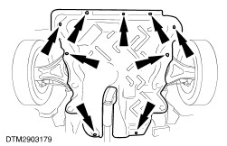
Remove the engine splash shield. | | | -
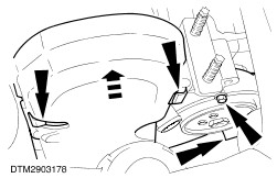
Remove the right-hand fender splash shield. | | | -
Remove the air conditioning compressor drive belt. For additional information, refer to Section 303-05 Accessory Drive. | | | -
Remove the fuel injector leak-off hoses. | | | -
Detach the fuel supply tube from the retaining clips. | | | -
Disconnect the fuel delivery tube unions from the fuel injectors. | | | -
Remove the delivery tubes. | | | -
Remove the accelerator cable adjuster clip. | | | -
Detach the accelerator cable from the retaining bracket. | | | -
Disconnect the accelerator cable from the fuel lever. | | | -
Disconnect the idle speed control cable from the idle lever. | | | -
Disconnect the fuel injection pump wiring harness electrical connector. | | | -
Disconnect the fuel supply tube from the fuel injection pump. | | | -
Disconnect the fuel return tube from the fuel injection pump. | | | -
Disconnect the turbocharger boost pressure actuator hose from the fuel injection pump. | | | -
Detach the turbocharger boost line. | | | -
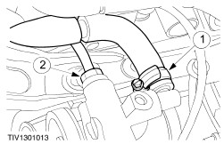
NOTE:Allow the fluid to drain into a suitable container. Disconnect the power steering hose and tube. - Disconnect the power steering hose.
- Disconnect the power steering tube.
| | | -
Remove the power steering pump drive belt. For additional information, refer to Section 303-05 Accessory Drive. | | | -
Remove the power steering pump drive pulley. | | | -
Remove the top engine mount. | | | -
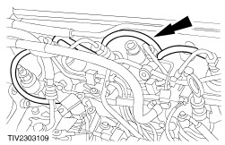
Disconnect the coolant hose from the water pump. | | | -
Remove the timing belt cover. | | | -
Turn the engine clockwise until the slot in the fuel injection pump drive gear reaches the 11 o'clock position. | | | -
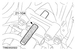
Install the TDC timing peg to the cylinder block. | | | -
CAUTION:When turning the engine to lock the crankshaft against the TDC timing peg, do so slowly to avoid bending the TDC timing peg. Turn the engine clockwise until the crankshaft locks against the TDC timing peg. | | | -
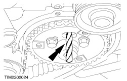
Install the drill bit to lock the fuel injection pump. | | | -
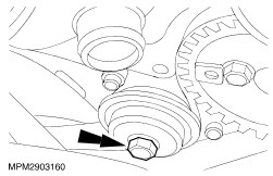
Loosen the fuel injection pump drive belt tensioner bolt to slacken the drive belt. | | | -
Tighten the fuel injection pump drive belt tensioner bolt. | | | -
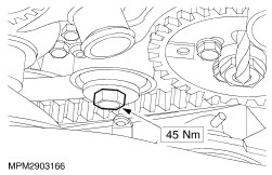
Remove the fuel injection pump drive gear retaining bolts. | | | -
Remove the drill bit from the fuel injection pump. | | | -
Remove the fuel injection pump drive gear and drive belt. | | | -
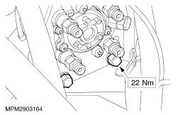
Remove the fuel injection pump retaining bolts. | | | -
Remove the fuel injection pump support bracket retaining bolts. | | | -
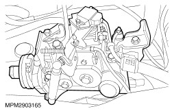
Remove the fuel injection pump. | Installation WARNING:Do not smoke or carry lighted tobacco or open flame of any type when working on or near any fuel related components. Highly flammable mixtures are always present and can ignite, resulting in possible personal injury. CAUTION:Diesel fuel injection equipment is manufactured to very precise tolerances and fine clearances. It is therefore essential that absolute cleanliness is observed when working with these components. Always fit blanking plugs to any open orifices or lines. | | -
Install the fuel injection pump. | | | -
Install the fuel injection pump support bracket retaining bolts. | | | -
NOTE:Do not fully tighten the fuel injection pump drive gear retaining bolts. Install the fuel injection pump drive gear - Make sure the slot in the drive gear aligns with the hole in the fuel injection pump drive flange.
| | | -
Install a new fuel injection pump drive belt. | | | -
Install the drill bit to lock the fuel injection pump. | | | -
Loosen the drive belt tensioner bolt to tension the drive belt. | | | -
NOTE:Make sure the elongated holes in the fuel injection pump drive gear are centralized with the retaining bolts. Tighten the fuel injection pump drive belt tensioner bolt. | | | -
Tighten the fuel injection pump drive gear retaining bolts. | | | -
Remove the drill bit from the fuel injection pump. | | | -
Remove the camshaft locking plate. | | | -
Remove the TDC timing peg from the cylinder block. | | | -
Turn the engine clockwise two full turns until the slot in the fuel injection pump drive gear reaches the 11 o'clock position. | | | -
Install the TDC timing peg to the cylinder block. | | | -
CAUTION:When turning the engine to lock the crankshaft against the TDC timing peg, do so slowly to avoid bending the TDC timing peg. Turn the engine clockwise until the crankshaft locks against the TDC timing peg. | | | -
Check the static timing. - Install the drill bit and the camshaft locking plate.
- If either the drill or the camshaft locking plate fail to enter their respective holes, repeat the timing procedure.
| | | -
Remove the drill bit from the fuel injection pump. | | | -
Remove the camshaft locking plate. | | | -
Remove the TDC timing peg from the cylinder block. | | | -
Connect the engine coolant hose. | | | -
Install the top engine mount. | | | -
Remove the engine support bar. | | | -
Install the power steering pump drive pulley. | | | -
Install the power steering pump drive belt. For additional information, refer to Section 303-05 Accessory Drive. | | | -
Install the power steering tube and hose. - Reconnect the power steering hose.
- Reconnect the power steering tube.
| | | -
Attach the turbocharger boost pressure actuator. | | | -
Connect the turbocharger boost hose to the fuel injection pump. | | | -
Connect the fuel return tube to the fuel injection pump. | | | -
Connect the fuel supply tube to the fuel injection pump. | | | -
Connect the fuel injection pump wiring harness electrical connector. | | | -
Connect the idle speed control cable. | | | -
Connect the accelerator cable. | | | -
Install the fuel delivery tubes to the fuel injection pump. | | | -
Connect the fuel delivery tube unions to the fuel injectors. | | | -
Attach the fuel supply tube to the retaining clips. | | | -
Install the fuel injector leak-off hoses. | | | -
Install the air conditioning compressor drive belt. For additional information, refer to Section 303-05 Accessory Drive. | | | -
Install the right-hand fender splash shield. | | | -
Install the engine splash shield. | | | -
Adjust the accelerator cable. | | | -
Check the engine idle speed and adjust as necessary. For additional information, refer to Idle Speed Adjustment in this section. | | |