| Disassembly and Assembly of Subassemblies Special Tool(s) | | Preload Gauge 205-067 (15-041) | | | Guide Studs 307-127 (17-026) | | | Gauge Bar, Shim Selection 307-300 (17-055) | | | Depth Gauge, Shim Selection 307-300-02 (17-055-02) | Materials Name Specification Automatic transmission fluid ESP-M2C166-H Disassembly 6 – Pump body separator plate 7 – Pump body separator plate gasket | | -
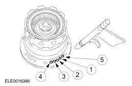
Remove and discard the seven pump support seal rings from the pump support. | | | -
Remove the six pump support bolts. | | | -
Separate the pump support and body assembly. - Remove the pump support.
- Remove the pump body separator plate gasket.
- Remove the pump body separator plate.
- Remove the pump body.
| | | -
Remove and discard the pump seal. | | | -
Remove the pump drive gear assembly. - Remove the pump drive gear insert.
- Remove the pump drive gear.
- Remove the pump driven gear.
| | | -
WARNING:Wear protective safety goggles when cleaning components with compressed air. Thoroughly clean all components and blow them dry with completely dry, regulated compressed air. | | | -
Inspect the pump body and gears for damage and wear. - Inspect the driven gear teeth.
- Inspect the drive gear teeth.
- Inspect the lubrication passages.
| | | -
Inspect the pump support apply circuit passages and lubrication passages. - Inspect the rear lubrication circuit.
- Inspect the reverse clutch circuit.
- Inspect the direct clutch circuit.
- Inspect the forward clutch circuit.
- Inspect the coast clutch circuit.
- Inspect the converter clutch bypass circuit.
| Assembly | | -
NOTE:The identification mark on the pump driven gear must be facing downward. Install the pump driven gear. | | | -
Install the pump drive gear assembly. - Install the pump drive gear.
- Install the pump drive gear insert.
| | | -
Using the special tool, measure the clearance between each gear and the pump body face. - If the clearance exceeds specification, install a new pump assembly.
| | | -
Install the special tool. | | | -
Align the pump support assembly. - Align the pump guide screws.
- Install the pump body.
- Install the pump body separator plate.
- Install the pump body separator plate gasket onto the pump body.
- Install the pump support.
| | | -
NOTE:Install the four pump support bolts in the pump support holes, and remove the guide studs. Then install the last two bolts. Install the six pump support bolts. | | | -
NOTE:Make sure that the white stripe on the pump seal is visible around the pump body circumference. Install the pump seal on the pump body. | | | -
NOTE:Make sure the pump support seal rings are overlapped correctly. Install the seven pump support seal rings. | | | -
Measure the pump rotational torque. - Install the pump drive shaft.
- Measure the pump rotational torque.
- Remove the pump drive shaft.
- If rotational torque exceeds the specification, disassemble and inspect the pump assembly for contamination or incorrect end clearance.
| | | -
Install the No.1 pump support thrust bearing. | | | -
Install the forward, coast and direct clutch cylinder and reverse clutch drum on the pump support. | | | -
WARNING:Wear protective safety goggles when cleaning components with compressed air. NOTE:With each application of air, you should hear the operation of the clutch pack. A hissing or high pitched squeal indicates that a seal is damaged or torn. Inspect to find the source and repair as necessary. Check the following passages of the forward, coast and direct clutch cylinder and reverse clutch drum with moisture - free compressed air, regulated to 276 kPa (40 psi). - Check the reverse clutch passage.
- Check the forward clutch passage.
- Check the direct clutch passage.
- Check the coast clutch passage.
- Check the fluid line from the torque converter lock-up clutch bypass.
| |