| Removal Special Tool(s) | | Spanner, for steering gear 211-186 (13013) | | | Driveshaft remover 308-192 (16057) | | | Adjuster, for shift lever 308-273 (16088A) | | | Spanner, for intake manifold 303-210 (21066) | | | Engine support bar 303-290 (21140) | | | Adapter for 303-290 303-290-01 (2114001) | | | Adapter for 303-290 303-290-02 (2114002) | | | Adapter for 303-290 303-290-03 (2114003) | General Equipment Retaining straps Transmission jack Auxiliary plugs Hand vacuum pump Materials Name Specification Cable ties Removal All Vehicles | | -
General notes. - Make a note of the radio keycode.
- Make a note of the pre-programmed radio stations.
- Sub-operations for particular variants which do not apply to all vehicles are marked clearly with a note.
- If necessary, cut cable ties and renew when installing the assembly.
| | | -
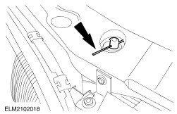
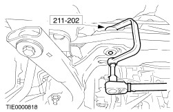
Hold the shift lever using special tool. - Shift the gear shift mechanism to neutral.
- Pull up the boot and bellows.
| | | -
Remove the air filter container. - Two positive crankcase ventilation (PCV) hoses
- Hose clamp on throttle body
- Vacuum hose
- Mass air flow (MAF) connector
- Intake air temperature (IAT) sensor connector
- Release from rubber mount and remove.
| | | -
NOTE:New nuts do not need fitting. Undo the nuts on both the suspension struts five turns. | | | -
Fasten the radiator on both sides (left-hand side shown). | | | -
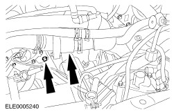
Remove the coolant pump cover. - Unclip the coolant hose.
- Remove the bolts.
- Take off the coolant pump cover.
| | | -
Detach the cables from the bracket. - Cruise control cable (if fitted)
- Accelerator cable
| | | -
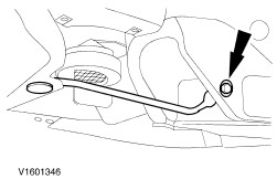
Detach the ground lead and lay it to one side. | | | -
Separate/pull off the vehicle speed sensor (VSS) connector and the reversing light switch. | | | -
Disconnect the starter motor. | | | -
Unscrew the two top flanged bolts. | | | -
Fit special tool (shown with battery removed). | | | -
CAUTION:Brake fluid may leak out. Observe the safety procedures for handling brake fluid. Detach the pressure line from the clutch slave cylinder. | | | -
Detach the left-hand transmission mounting bracket from the transmission. | | | -
Drain off the transmission fluid. - Re-tighten the drain plug.
| | | -
Remove the rear three-way catalytic converter. | | | -
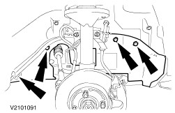
Remove the lower wheel arch trim panels (right-hand side shown without front wheel). | | | -
CAUTION:Do not damage the boots and the ABS sensor ring. Remove the stabiliser bar connecting link and the lower suspension arm ball joint from both sides (left-hand side shown without front wheel). | | | -
Remove the lower radiator cover. | | | -
Remove the bumper braces from the subframe. | Vehicles with air conditioning | | -
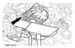
Remove the air-conditioning dryer. - Unscrew the bolts and tie the air-conditioning dryer to the side.
| | | -
Remove the oil line bracket from the subframe. | | | -
Remove the left-hand engine roll restrictor. - Unscrew the nuts.
- Remove the centre bolt.
| | | -
Remove the left-hand engine roll restrictor bracket. | | | -
Remove the right-hand engine roll restrictor. - Remove the centre bolt.
- Remove the bolts.
- Remove the right-hand engine roll restrictor.
| | | -
Remove the right-hand engine roll restrictor bracket. | | | -
Undo the bolts and lower the subframe at the rear. | | | -
Remove the steering gear heat shield. | | | -
Remove the steering gear and tie it up (two bolts; left-hand side shown). | | | -
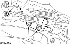
Detach the gearshift cable and the selector cable from the transmission. - Detach the gearshift cable and selector cable.
- Remove the nuts.
- Detach the bracket.
| | | -
WARNING:Support the subframe using the transmission jack. Place a suitable wooden block underneath. Fully unscrew the bolts and remove the subframe. | | | -
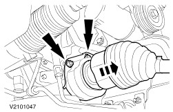
CAUTION:The inner joint must not be bent more than 18 degrees, the outer one no more than 45 degrees. Remove the right-hand front axle driveshaft centre bearing. - Detach the right-hand front axle driveshaft from the centre bearing and tie it up.
- Remove the centre bearing together with the intermediate shaft (two nuts).
| | | -
CAUTION:The inner joint must not be bent more than 18 degrees, the outer one no more than 45 degrees. Detach the left-hand driveshaft. - Detach the left-hand driveshaft using special tool and tie it up.
| | | -
Unscrew the bottom three rear flanged bolts (right-hand engine roll restrictor bracket shown installed). | | | -
Unscrew the bottom three front flanged bolts (left-hand engine roll restrictor bracket shown installed). | | | -
Lower the engine and transmission assembly slightly using special tool 303-290. | | | -
Remove any attachments or add-ons that are fitted to the transmission. - Starter (two bolts).
- VSS
| |