| Diagnosis and Testing Worldwide Diagnostic System (WDS) Inspection and Verification NOTE:If the navigation system display module displays either of the following: - serial number(s) are incompatible
- vehicle identification number (VIN) does not match
NOTE:Use the WDS to configure the navigation system display module and the navigation digital versatile disc (DVD) unit to each other. - Verify the customer concern.
- Visually inspect for obvious signs of mechanical or electrical damage.
Visual Inspection Chart | Mechanical | Electrical | - Navigation system display module
- Audio unit
- Navigation system DVD unit
- Antenna
- Steering column audio controls
| - Fuse(s)
- Wiring harness
- Electrical connector(s)
- Navigation system display module
- Audio unit
- Navigation system DVD unit
- Steering column audio controls
- Central junction box (CJB)
| - If an obvious cause for an observed or reported concern is found, correct the cause (if possible) before proceeding to the next step.
- If the cause is not visually evident, refer to the Self-Diagnostic Mode.
Self-Diagnostic Mode NOTE:It is necessary to carry out part of the system diagnosis outside the workshop. Make sure that there are no large buildings/obstructions or metal objects in the immediate vicinity. - Turn the ignition switch to position II.
- To access the diagnostic menu, PRESS and HOLD the MENU button for approximately 10 seconds, until a audible beep is heard and the screen changes to the personal identification number (PIN) number display.
- ENTER the following PIN number on the display to access the additional diagnostic menus: 6414.
- PRESS the ENTER button on the display screen to confirm PIN number input.
The display screen will show the following sub-menu(s): - General Info
- Manual Check
- Display Info
- Navigation Info
- S/W Update
- Self Check
- TOUCH the display screen to select the required sub-menu.
Additional menus can be accessed from the following sub-menus: General Info This sub-menu contains vehicle configuration information. The additional menus from this sub-menu are as follows: - Audio Diagnostics - Allows audio unit diagnosis
Manual Check This sub-menu allows access to key test screens. The additional menus from this sub-menu are as follows: - DIAGNOSTIC ERROR CODES - This will display a list of all set diagnostic trouble codes (DTC)s.
- NAV RGB TEST - Display color confirmation.
- TOUCH SCREEN CHECK - Allows the display touch calibration.
- DISPLAY HARDKEY CHECK - On screens icons are illuminated when a hard key is pressed.
Display Info This sub-menu contains software version information for the display. Navigation Info This sub-menu allows access to the global positioning system (GPS) information screens. The additional menus from this sub-menu are as follows: - RESET POSITION - Allows the vehicle position to be reset to the current map DVD default country (Belgium).
- VEHICLE/GYRO SIGNALS - Displays the vehicle direction, speed and distance. Also displays the gyro information.
- GPS INFORMATION - Displays the GPS satellites signals to the navigation system and their position.
S/W Update This sub-menu allows the update of the navigation system DVD unit software from a separate DVD ROM sent when an update is required and is available. This cannot be done from the normal navigation system DVD ROM. Self-Check This sub-menu displays error codes detected after an internal self-diagnostic check of the navigation DVD unit. - Turn the ignition switch to position 0 to exit the diagnostic menu.
- If the cause is not visually evident after the Self-Diagnostic Mode, connect the WDS to the data link connector (DLC).
- Retrieve the DTCs and refer to the DTC Index Chart.
Diagnostic Trouble Code (DTC) Index Chart - Navigation System Display | DTC | Description/Condition | Possible Source | Action | | B1342 | Display defective | Navigation system display module | INSTALL a new navigation system display module.
REFER to: Navigation System Display Module - Vehicles With: DVD Navigation System with Touchscreen (415-01 Information and Entertainment System, Removal and Installation).
| | B2995 | Video feed missing | Navigation system DVD unit or navigation system display module signal | GO to Pinpoint Test B. | Diagnostic Trouble Code (DTC) Index Chart - Navigation system Module | DTC | Description/Condition | Possible Source | Action | | B1342 | Navigation system display module failure | Navigation system display module | INSTALL a new navigation system display module.
REFER to: Navigation System Display Module - Vehicles With: DVD Navigation System with Touchscreen (415-01, Removal and Installation).
| | B2204 | GPS antenna connection open or short circuit | Antenna fault open or short circuit | CHECK the navigation system antenna connections and antenna base ground connection. TEST the system for normal operation. IF the concern persists, INSTALL a new navigation system antenna cable. | | B2477 | Module configuration failure | Navigation configuration failure | Refer to the WDS. | - If the cause is not visually evident, verify the symptom and refer to the Symptom Chart.
Symptom Chart | Symptom | Possible Sources | Action | | The navigation system display module shows incomplete street/map information | * DVD ROM. | * CHECK the navigation DVD ROM level. * INSPECT the DVD ROM for damage. INSTALL a new DVD ROM. TEST the system for normal operation. | | Navigation system will not switch on | * Instrument cluster. | * REFER to the WDS. | | * Circuit(s). * Navigation system display module. | * | | Navigation system does not operate correctly | * Instrument cluster. | * REFER to the WDS. | | * Circuit(s). * Navigation system display module. * Navigation system DVD unit. | * | | The audio unit is inoperative/does not operate correctly | * Instrument cluster. * Audio unit. * Navigation system display module. * Navigation system DVD unit. | * CHECK all communication between the instrument cluster, audio unit, navigation system display module and navigation system DVD unit. REFER to the WDS. | | * Compact disc (CD) changer. | * REFER to: Information and Entertainment System (415-00 Information and Entertainment System - General Information, Diagnosis and Testing). | | The display is blank | * Instrument cluster. | * REFER to WDS. | | * Navigation system display module. * Navigation system DVD unit. | * | | Poor quality/distorted sound from one or more speakers (not all speakers) | * Speaker(s). * Circuit. * Audio unit. | * REFER to: Information and Entertainment System (415-00 Information and Entertainment System - General Information, Diagnosis and Testing). | | No sound from all speakers | * Audio unit. | * INSTALL a new audio unit.
REFER to: Navigation System Display Module - Vehicles With: DVD Navigation System with Touchscreen (415-01 Information and Entertainment System, Removal and Installation).
TEST the system for normal operation. | | No sound from one or more of the speakers (not all speakers) | * Speaker(s). * Circuit. * Audio unit. | * REFER to: Information and Entertainment System (415-00 Information and Entertainment System - General Information, Diagnosis and Testing). | | The auxiliary audio control is inoperative/does not operate correctly. | * Circuit. * Audio control switch. * Audio unit. | * REFER to: Information and Entertainment System (415-00 Information and Entertainment System - General Information, Diagnosis and Testing). | Pinpoint Tests CAUTION:Remove the DVD ROM before removing the navigation system DVD unit for circuit testing. Failure to follow this instruction may result in damage to the DVD ROM. NOTE:Use a digital multimeter for all electrical measurements. | PINPOINT TEST A : NAVIGATION SYSTEM WILL NOT SWITCH ON | | TEST CONDITIONS | DETAILS/RESULTS/ACTIONS | | A1: CHECK THE NAVIGATION SYSTEM DISPLAY MODULE FOR VOLTAGE | | | 1 Disconnect Navigation System Display Module C2ME03-F. | | | 2 Ignition switch in position I. | | | 3 Measure the voltage between the navigation system display module C2ME03-F pin 1, circuit SBP06J (BN/RD), harness side and ground; and between the navigation system display module C2ME03-F pin 2, circuit CDC33D (VT/GN), harness side and ground. | | | Are the voltages greater than 10 volts? Yes No REPAIR circuit SBP06J (BN/RD) or circuit CDC33D (VT/GN). TEST the system for normal operation. | | A2: CHECK THE NAVIGATION SYSTEM DISPLAY MODULE GROUND CIRCUITS FOR OPEN CIRCUIT | | | 1 Ignition switch in position 0. | | | 2 Measure the resistance between the navigation system display module C2ME03-F pin 11, circuit GD138BF (BK/WH), harness side and ground; and between the navigation system display module C2ME03-F pin 12, circuit GD138BG (BK/WH), harness side and ground. | | | Are the resistances less than 1 ohm? Yes INSTALL a new navigation system display module.
REFER to: Navigation System Display Module - Vehicles With: DVD Navigation System with Touchscreen (415-01 Information and Entertainment System, Removal and Installation).
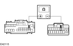
TEST the system for normal operation. No REPAIR circuit GD138BF (BK/WH) or GD138BG (BK/WH). TEST the system for normal operation. | | PINPOINT TEST B : NAVIGATION SYSTEM DOES NOT OPERATE CORRECTLY | | TEST CONDITIONS | DETAILS/RESULTS/ACTIONS | | B1: CHECK THE NAVIGATION SYSTEM DVD UNIT FOR VOLTAGE | | | 1 Disconnect Navigation System DVD Unit C2ME04. | | | 2 Measure the voltage between the navigation system DVD unit C2ME04 pin 1, circuit SBP06F (BN/RD), harness side and ground. | | | Is the voltage greater than 10 volts? Yes No REPAIR the circuit SBP06F (BN/RD). TEST the system for normal operation. | | B2: CHECK THE NAVIGATION SYSTEM DVD UNIT GROUND CIRCUIT FOR OPEN CIRCUIT | | | 1 Measure the resistance between the navigation system DVD unit C2ME04 pin 13, circuit GD138BH (BK/WH), harness side and ground. | | | Is the resistance less than 1 ohm? Yes No REPAIR the circuit GD138BH (BK/WH). TEST the system for normal operation. | | B3: CHECK CIRCUIT CMN13A (YE/OG) FOR OPEN CIRCUIT | | | 1 Disconnect Navigation System Display Module C2ME03-F. | | | 2 Measure the resistance between the navigation system display module C2ME03-F pin 4, circuit CMN13A (YE/OG), harness side and the navigation system DVD unit C2ME04 pin 2, circuit CMN13A (YE/OG), harness side. | | | Is the resistance less than 5 ohms? Yes No REPAIR the circuit. TEST the system for normal operation. | | B4: CHECK CIRCUIT DMN08A (NO) FOR OPEN CIRCUIT | | | 1 Measure the resistance between the navigation system display module C2ME03-F pin 18, circuit DMN08A (NO), harness side and the navigation system DVD unit C2ME04 pin 23, circuit DMN08A (NO), harness side. | | | Is the resistance less than 1 ohm? Yes No REPAIR the circuit. TEST the system for normal operation. | | B5: CHECK CIRCUIT VMN08A (VT/GY) FOR OPEN CIRCUIT | | | 1 Measure the resistance between the navigation system display module C2ME03-F pin 8, circuit VMN08A (VT/GY), harness side and the navigation system DVD unit C2ME04 pin 10, circuit VMN08A (VT/GY), harness side. | | | Is the resistance less than 1 ohm? Yes No REPAIR the circuit. TEST the system for normal operation. | | B6: CHECK CIRCUIT VMN09A (VT/GY) FOR OPEN CIRCUIT | | | 1 Measure the resistance between the navigation system display module C2ME03-F pin 19, circuit VMN09A (VT/GY), harness side and the navigation system DVD unit C2ME04 pin 22, circuit VMN09A (VT/GY), harness side. | | | Is the resistance less than 1 ohm? Yes No REPAIR the circuit. TEST the system for normal operation. | | B7: CHECK CIRCUIT VMN10A (BU/WH) FOR OPEN CIRCUIT | | | 1 Measure the resistance between the navigation system display module C2ME03-F pin 20, circuit VMN10A (BU/WH), harness side and the navigation system DVD unit C2ME04 pin 9, circuit VMN10A (BU/WH), harness side. | | | Is the resistance less than 1 ohm? Yes No REPAIR the circuit. TEST the system for normal operation. | | B8: CHECK CIRCUIT VMN11A (GR/RD) FOR OPEN CIRCUIT | | | 1 Measure the resistance between the navigation system display module C2ME03-F pin 10, circuit VMN11A (GR/RD), harness side and the navigation system DVD unit C2ME04 pin 21, circuit VMN11A (GR/RD), harness side. | | | Is the resistance less than 1 ohm? Yes No REPAIR the circuit. TEST the system for normal operation. | | B9: CHECK CIRCUIT VMN12A (GN/BK) FOR OPEN CIRCUIT | | | 1 Measure the resistance between the navigation system display module C2ME03-F pin 9, circuit VMN12A (GN/BK), harness side and the navigation system DVD unit C2ME04 pin 8, circuit VMN12A (GN/BK), harness side. | | | Is the resistance less than 1 ohm? Yes No REPAIR the circuit. TEST the system for normal operation. If the concern persists, INSTALL a new navigation system display module.
REFER to: Navigation System Display Module - Vehicles With: DVD Navigation System with Touchscreen (415-01 Information and Entertainment System, Removal and Installation).
TEST the system for normal operation. | | B10: CHECK CIRCUIT RMN14A (BU/RD) FOR OPEN CIRCUIT | | | 1 Connect Navigation System Display Module C2ME03-F. | | | 2 Disconnect Audio Unit C2ME03-C. | | | 3 Measure the resistance between the navigation system DVD unit C2ME04 pin 12, circuit RMN14A (BU/RD), harness side and the audio unit C2ME03-C pin 9, circuit RMN14A (BU/RD), harness side. | | | Is the resistance less than 1 ohm? Yes No REPAIR the circuit. TEST the system for normal operation. | | B11: CHECK CIRCUIT VMN14A (BN/RD) FOR OPEN CIRCUIT | | | 1 Measure the resistance between the navigation system DVD unit C2ME04 pin 11, circuit VMN14A (BN/RD), harness side and the audio unit C2ME03-C pin 3, circuit VMN14A (BN/RD), harness side. | | | Is the resistance less than 1 ohm? Yes INSTALL a new navigation system DVD unit.
REFER to: Navigation System Digital Versatile Disc (DVD) Unit (415-01 Information and Entertainment System, Removal and Installation).
TEST the system for normal operation. No REPAIR the circuit. TEST the system for normal operation. If the concern persists, INSTALL a new audio unit.
REFER to: Navigation System Display Module - Vehicles With: DVD Navigation System with Touchscreen (415-01 Information and Entertainment System, Removal and Installation).
TEST the system for normal operation. | |