| PINPOINT TEST A : AUTOMATIC HEADLAMPS INOPERATIVE |
| TEST CONDITIONS | DETAILS/RESULTS/ACTIONS |
| A1: DETERMINE THE FAULT CONDITION |
| | 1 Ignition switch in position II. |
| | 2 SWITCH ON dipped beam. |
| | 3 CHECK the operation of the dipped beam and the parking lamps. |
| | 4 SWITCH ON the automatic headlamps. |
| | 5 Cover rain sensor with opaque material to simulate insufficient light conditions. |
| | 6 CHECK the operation of the dipped beam and the parking lamps. |
| | Is the normal dipped beam operative? Yes Automatic headlamps inoperative: GO to A2. No REFER to: Scheinwerfer (417-01, Diagnosis and Testing). |
| A2: CHECK FUSE F1 (5 A) (CJB). |
| | 1 Ignition switch in position 0. |
| | 2 Disconnect Fuse F1 (5 A) (CJB). |
| | 3 CHECK Fuse F1 (5 A) (CJB). |
| | Is the fuse OK.? Yes No RENEW fuse F1 (5 A) (CJB) and CHECK the operation of the system. If the fuse blows again, LOCATE and RECTIFY the short to ground using the Wiring Diagrams. CHECK the operation of the system. |
| A3: CHECK THE VOLTAGE SUPPLY TO FUSE F1 (5 A) (CJB) FOR OPEN CIRCUIT |
| | 1 Connect Fuse F1 (5 A) (CJB). |
| | 2 Ignition switch in position II. |
| | 3 Measure the voltage between fuse F1 (5 A) (CJB) and ground. |
| | Does the meter display battery voltage? Yes No RENEW THE CJB. CHECK the operation of the system. |
| A4: CHECK VOLTAGE SUPPLY TO RAIN SENSOR FOR OPEN CIRCUIT |
| | 1 Ignition switch in position 0. |
| | 2 Disconnect Rain sensor from connector C9RW06. |
| | 3 Ignition switch in position II. |
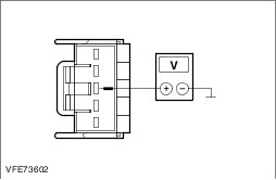
| | 4 Measure the voltage between the rain sensor, connector C9RW06, pin 3, circuit CBP01B (BU), wiring harness side and ground. |
| | Does the meter display battery voltage? Yes No |
| A5: CHECK CIRCUIT CBP01B (BU) BETWEEN CENTRAL JUNCTION BOX (CJB) AND RAIN SENSOR FOR OPEN CIRCUIT |
| | 1 Ignition switch in position 0. |
| | 2 Disconnect CJB from connector C1BP02H. |
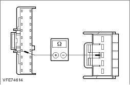
| | 3 Measure the resistance between the CJB, connector C1BP02H, pin 17, circuit CBP01B (BU), wiring harness side and the rain sensor, connector C9RW06, pin 3, circuit CBP01B (BU), wiring harness side. |
| | Is a resistance of less than 2 Ohms registered? Yes RENEW THE CJB. CHECK the operation of the system. No LOCATE and RECTIFY the break in the circuit between CJB and the rain sensor using the Wiring Diagrams. CHECK the operation of the system. |
| A6: CHECK GROUND CONNECTION OF RAIN SENSOR FOR OPEN CIRCUIT |
| | 1 Ignition switch in position 0. |
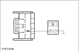
| | 2 Measure the resistance between the rain sensor, connector C9RW06, pin 2, circuit GD138V(BK/WH), wiring harness side and ground. |
| | Is a resistance of less than 2 Ohms registered? Yes No LOCATE and RECTIFY the break in the circuit between the rain sensor and soldered connection SP523 using the Wiring Diagrams. CHECK the operation of the system. |
| A7: CHECK CIRCUIT (LIN 2 BUS) VRW26A (BN/YE) BETWEEN THE GENERIC ELECTRONIC MODULE (GEM) AND THE RAIN SENSOR FOR SHORT CIRCUIT TO BATTERY VOLTAGE |
| | 1 Disconnect GEM from connector C1BP02H. |
| | 2 Ignition switch in position II. |
| | 3 Measure the voltage between the rain sensor, connector C9RW06, pin 1, circuit VRW26A (BN/YE), wiring harness side and ground. |
| | Does the meter display battery voltage? Yes LOCATE and RECTIFY the short to battery voltage in the circuit between the (GEM) and the rain sensor using the Wiring Diagrams. CHECK the operation of the system. No |
| A8: CHECK CIRCUIT (LIN 2 BUS) VRW26A (BN/YE) BETWEEN THE GENERIC ELECTRONIC MODULE (GEM) AND THE RAIN SENSOR FOR SHORT CIRCUIT TO GROUND |
| | 1 Ignition switch in position 0. |
| | 2 Measure the resistance between the rain sensor, connector C9RW06, pin 1, circuit VRW26A (BN/YE), wiring harness side and ground. |
| | Is a resistance of more than 10,000 Ohm measured? Yes No LOCATE and RECTIFY the short to ground in the circuit between the GEM and the rain sensor using the Wiring Diagrams. CHECK the operation of the system. |
| A9: CHECK CIRCUIT (LIN 2 BUS) VRW26A (BN/YE) BETWEEN THE GENERIC ELECTRONIC MODULE (GEM) AND THE RAIN SENSOR FOR OPEN CIRCUIT |
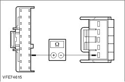
| | 1 Measure the resistance between the GEM, connector C1BP02H, pin 8, circuit VRW26A (BN/YE), wiring harness side and the rain sensor, connector C9RW06, pin 1, circuit VRW26A (BN/YE), wiring harness side. |
| | Is a resistance of less than 2 Ohms registered? Yes RENEW rain sensor. CHECK the operation of the system. If the concern persists, CHECK the CJB using WDS, RENEW if necessary. CHECK the operation of the system. No LOCATE and RECTIFY the break in the circuit between GEM and the rain sensor using the Wiring Diagrams. CHECK the operation of the system. |