| Diagnosis and Testing Refer to Wiring Diagrams Section 417-01, for schematic and connector information. Special Tool(s) | | Terminal Probe Kit 29-011A | Inspection and Testing NOTE:The generic electronic module (GEM) is part of the central junction box (CJB). NOTE:If a new GEM module is being installed, the new module must be configured following installation. For this purpose, the vehicle-specific data is read out of the module to be changed using WDS and is transferred to the new module. REFER to: Modul-Konfiguration (418-01, General Procedures), Zentralelektrikmodul (GEM) (419-10, Diagnosis and Testing). NOTE:Before reading out the vehicle-specific data make sure that all electrical connections in the vehicle are reconnected so that the module and WDS can communicate correctly. - Verify the customer concern.
- Visually inspect for obvious signs of electrical damage.
Visual Inspection Chart | Electrical | - Fuse(s)
- Bulb(s)
- Connector
- Switch
- Wiring loom
| - Resolve any obvious causes or concerns found during the visual inspection before carrying out any further tests.
- If the cause of the concern cannot be found by visual inspection, continue with the symptom chart.
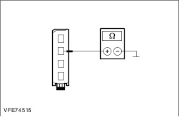
Symptom chart Symptom chart | Symptom | Possible Sources | Action | | The Backup Lamps Are Inoperative | * Fuse(s) * Backup lamp switch * Circuit(s) * Central Junction Box (CJB) | * | | One backup lamp is inoperative | * Circuit(s) * Tailgate lamps assembly | * | | The Backup Lamps Are On Continuously | * Circuit(s) * Backup lamp switch * Trailer socket | * | Pinpoint test NOTE:Use a digital multimeter for all electrical measurements. | PINPOINT TEST A : THE BACKUP LAMPS ARE INOPERATIVE | | TEST CONDITIONS | DETAILS/RESULTS/ACTIONS | | A1: CHECK FUSE F11 (7.5 A) (SJB) | | | 1 Ignition switch in position 0. | | | 2 Disconnect Fuse F11 (7.5 A) (SJB). | | | 3 CHECK Fuse F11 (7.5 A) (SJB). | | | Is the fuse OK.? Yes No INSTALL A NEW fuse F11 (7.5 A) (SJB). CHECK system operates correctly If the fuse blows again, LOCATE and RECTIFY short using the Wiring Diagrams. CHECK system operates correctly | | A2: CHECK THE VOLTAGE SUPPLY TO FUSE F11 (7.5 A) (SJB) FOR OPEN CIRCUIT | | | 1 Connect Fuse F11 (7.5 A) (SJB). | | | 2 Ignition switch in position II. | | | 3 Measure the voltage between fuse F11 (7.5 A) (SJB) and ground. | | | Does the meter display battery voltage? Yes No LOCATE AND RECTIFY the break in the voltage supply of fuse F11 (7.5 A) (SJB) using the Wiring Diagrams. CHECK system operates correctly | | A3: RULE OUT THE BACKUP LAMP SWITCH AS A POSSIBLE CAUSE OF THE FAULT | | | 1 Ignition switch in position 0. | | | 2 Disconnect Backup lamp switch from. - Manual transmission (SIGMA): Connector C1ET47B
- Manual transmission (all other variants): Connector C1ET47A
| | | 3 Manual transmission (SIGMA): Connect a fused (5 A) jumper lead at the backup lamp switch, connector C1ET47B, between pin 1, circuit (BU), wiring harness side and ground. | | | 4 Manual transmission (all other variants): Connect a fused jumper lead (5 A) at the backup lamp switch, connector C1ET47A, between pin 1, circuit (BU), wiring harness side and pin 2, circuit GD120S (BK/GN) / GD120B (BK/GN), wiring harness side. | | | 5 Ignition switch in position II. | | | Are the backup lamps illuminated? Yes INSTALL A NEW backup lamp switch. CHECK system operates correctly No - Manual transmission (SIGMA): GO to A5. - Manual transmission (all other variants): GO to A4. | | A4: CHECK THE GROUND CONNECTION OF THE BACKUP LAMP SWITCH FOR OPEN CIRCUIT | | | 1 Ignition switch in position 0. | | | 2 Measure the resistance between the backup lamp switch, connector C1ET47A, pin 2, circuit GD120S (BK/GN) / GD120B (BK/GN), wiring harness side and ground. | | | Is a resistance of less than 2 Ohm registered? Yes No LOCATE and RECTIFY the break in the circuit between the backup lamp switch and soldered connection SP358 using the Wiring Diagrams. CHECK system operates correctly | | A5: CHECK THE CIRCUIT BETWEEN THE SMART JUNCTION BOX AND THE BACKUP LAMP SWITCH FOR OPEN CIRCUIT | | | 1 Ignition switch in position 0. | | | 2 Disconnect Smart Junction Box from connector C1BP02A. | | | 3 Connect Backup lamp switch to. - Manual transmission (SIGMA): Connector C1ET47B
- Manual transmission (all other variants): Connector C1ET47A
| | | 4 ENGAGE the reverse gear. | | | 5 Measure the resistance between the Smart Junction Box, connector C1BP02A, pin 26, circuit CET47B (BU), wiring harness side and ground. | | | Is a resistance of less than 2 Ohm registered? Yes No LOCATE and RECTIFY the break in the circuit between the Smart Junction Box and the backup lamp switch with the aid of the Wiring Diagrams. CHECK system operates correctly | | A6: CHECK THE SHARED GROUND OF THE BACKUP LAMPS FOR OPEN CIRCUIT | | | 1 Disconnect Left-hand rear lamp assembly from connector C4LS35. | | | 2 Measure the resistance between the left-hand rear lamp assembly (tailgate), connector C4LS35, pin 2, circuit GD150P (BK/WH), wiring harness side and ground. | | | Is a resistance of less than 2 Ohm registered? Yes INSTALL A NEW Smart Junction Box. CHECK system operates correctly No LOCATE and RECTIFY the break in the circuit between soldered connection SP534 and ground connection G4D149 with the aid of the Wiring Diagrams. CHECK system operates correctly | | PINPOINT TEST B : ONE BACKUP LAMP IS INOPERATIVE | | TEST CONDITIONS | DETAILS/RESULTS/ACTIONS | | B1: DETERMINE CONDITIONS UNDER WHICH THE FAULT OCCURS | | | 1 Ignition switch in position II. | | | 2 ENGAGE the reverse gear. | | | 3 CHECK the backup lamps. | | | Is the left-hand backup lamp inoperative? Yes No Right-hand backup lamp inoperative: GO to B5. | | B2: CHECK THE POWER SUPPLY OF THE LEFT-HAND TAILGATE LAMP ASSEMBLY FOR OPEN CIRCUIT | | | 1 Ignition switch in position 0. | | | 2 Disconnect Left-hand tailgate lamp assembly from connector C4LS35. | | | 3 Ignition switch in position II. | | | 4 ENGAGE reverse gear. | | | 5 Measure the voltage between the left-hand tailgate lamp assembly, connector C4LS35, pin 4, circuit A_CLS10A (GN/BN), wiring harness side and ground. | | | Does the meter display battery voltage? Yes No | | B3: CHECK THE POWER SUPPLY OF THE LEFT-HAND TAILGATE LAMP ASSEMBLY FOR OPEN CIRCUIT | | | 1 Ignition switch in position 0. | | | 2 Disconnect Smart Junction Box from connector C1BP02B. | | | 3 Measure the resistance between the Smart Junction Box, connector C1BP02B, pin 73, circuit A_CLS10B (GN/BN), wiring harness side and the left-hand tailgate lamp assembly, connector C4LS35, pin 4, circuit A_CLS10A (GN/BN), wiring harness side. | | | Is a resistance of less than 2 Ohm registered? Yes INSTALL A NEW Smart Junction Box. CHECK system operates correctly No LOCATE and RECTIFY the break in the circuit between the Smart Junction Box and the tailgate lamp assembly with the aid of the Wiring Diagrams. CHECK system operates correctly | | B4: CHECK THE GROUND CONNECTION OF THE LEFT-HAND TAILGATE LAMP ASSEMBLY FOR OPEN CIRCUIT | | | 1 Ignition switch in position 0. | | | 2 Measure the resistance between the left-hand tailgate lamp assembly, connector C4LS35, pin 2, circuit GD150P (BK/WH), wiring harness side and ground. | | | Is a resistance of less than 2 Ohm registered? Yes INSTALL A NEW tailgate lamp unit. CHECK system operates correctly No LOCATE and RECTIFY the break in the circuit between the tailgate lamp unit and soldered connection SP534 with the aid of the Wiring Diagrams. CHECK system operates correctly | | B5: CHECK THE POWER SUPPLY OF THE RIGHT-HAND TAILGATE LAMP ASSEMBLY FOR OPEN CIRCUIT | | | 1 Ignition switch in position 0. | | | 2 Disconnect Right-hand tailgate lamp assembly from connector C4LS36. | | | 3 Ignition switch in position II. | | | 4 ENGAGE the reverse gear. | | | 5 Measure the voltage between the right-hand tailgate lamp assembly, connector C4LS36, pin 4, circuit CLS10A (GN/BN), wiring harness side and ground. | | | Does the meter display battery voltage? Yes No | | B6: CHECK THE POWER SUPPLY OF THE RIGHT-HAND TAILGATE LAMP ASSEMBLY FOR OPEN CIRCUIT | | | 1 Ignition switch in position 0. | | | 2 Disconnect Smart Junction Box from connector C1BP02B. | | | 3 Measure the resistance between the Smart Junction Box, connector C1BP02B, pin 62, circuit CLS10B (GN/BN), wiring harness side and the right-hand tailgate lamp assembly, connector C4LS36, pin 4, circuit CLS10A (GN/BN), wiring harness side. | | | Is a resistance of less than 2 Ohm registered? Yes INSTALL A NEW Smart Junction Box. CHECK system operates correctly No LOCATE and RECTIFY the break in the circuit between the Smart Junction Box and the tailgate lamp assembly with the aid of the Wiring Diagrams. CHECK system operates correctly | | B7: CHECK THE GROUND CONNECTION OF THE RIGHT-HAND TAILGATE LAMP ASSEMBLY FOR OPEN CIRCUIT | | | 1 Ignition switch in position 0. | | | 2 Measure the resistance between the right-hand tailgate lamp unit, connector C4LS36, pin 2, circuit GD150W (BK/WH), wiring harness side and ground. | | | Is a resistance of less than 2 Ohm registered? Yes INSTALL A NEW tailgate lamp unit. CHECK system operates correctly No LOCATE and RECTIFY the break in the circuit between the tailgate lamp unit and soldered connection SP534 with the aid of the Wiring Diagrams. CHECK system operates correctly | | PINPOINT TEST C : THE BACKUP LAMPS ARE PERMANENTLY LIT | | TEST CONDITIONS | DETAILS/RESULTS/ACTIONS | | C1: RULE OUT THE BACKUP LAMP SWITCH AS A POSSIBLE CAUSE OF THE FAULT | | | 1 Ignition switch in position 0. | | | 2 Disconnect Backup lamp switch from:. - Manual transmission (SIGMA): Connector C1ET47B
- Manual transmission (all other variants): Connector C1ET47A
| | | 3 Ignition switch in position II. | | | 4 CHECK the backup lamps. | | | Are the backup lamps lit? Yes No INSTALL A NEW backup lamp switch. CHECK system operates correctly | | C2: NARROW DOWN THE CAUSE OF THE FAULT | | | 1 Ignition switch in position 0. | | | 2 Disconnect Smart Junction Box from connector C1BP02A. | | | 3 Disconnect Smart Junction Box from connector C1BP02B. | | | 4 Ignition switch in position II. | | | Is one backup lamp permanently lit? Yes - Left-hand backup lamp permanently lit: LOCATE and RECTIFY the short to battery voltage in the circuits between the Smart Junction Box and the left-hand backup lamp with the aid of the Wiring Diagrams. CHECK system operates correctly - Right-hand backup lamp permanently lit: LOCATE and RECTIFY the short to battery voltage in the circuits between the Smart Junction Box and the right-hand backup lamp with the aid of the Wiring Diagrams. CHECK system operates correctly No | | C3: CHECK THE CIRCUIT BETWEEN THE SMART JUNCTION BOX AND THE BACKUP LAMP SWITCH FOR SHORT TO GROUND | | | 1 Ignition switch in position 0. | | | 2 Measure the resistance between the Smart Junction Box, connector C1BP02B, pin 26, circuit CET47B (BU), wiring harness side and ground. | | | Is a resistance of more than 10,000 Ohm measured? Yes INSTALL A NEW Smart Junction Box. CHECK system operates correctly No LOCATE and REPAIR the short to ground using the Wiring Diagrams. CHECK system operates correctly | |