| PINPOINT TEST C : SINGLE OR MULTIPLE TURN SIGNAL LAMPS INOPERATIVE |
| TEST CONDITIONS | DETAILS/RESULTS/ACTIONS |
| C1: DETERMINE THE CONDITION UNDER WHICH THE FAULT OCCURS |
| | 1 Ignition switch in position II. |
| | 2 CHECK the turn signal lamps. |
| | 3 SWITCH ON the left-hand turn signal. |
| | 4 SWITCH ON the right-hand turn signal. |
| | Is one or more turn signal lamp on the left-hand side inoperative? Yes - All turn signal lamps on left-hand side inoperative: CHECK and if necessary RENEW the steering wheel/steering column switch. CHECK system operates correctly If the concern persists:
REFER to: Kommunikations-Netzwerk (418-00, Diagnosis and Testing).
- Left-hand front turn signal lamp is inoperative: GO to C2. - Left-hand rear turn signal lamp is inoperative: GO to C5. - Integrated turn signal lamp in the left-hand exterior mirror is inoperative: GO to C8. No - All turn signal lamps on right-hand side inoperative: CHECK and if necessary RENEW the steering wheel/steering column switch. CHECK system operates correctly If the concern persists:
REFER to: Kommunikations-Netzwerk (418-00, Diagnosis and Testing).
- Right-hand front turn signal lamp is inoperative: GO to C16. - Right-hand rear turn signal lamp is inoperative: GO to C19. - Integrated turn signal lamp in the right-hand exterior mirror is inoperative: GO to C22. - Integrated turn signal lamps in the exterior mirrors on both sides are inoperative: GO to C30. |
| C2: CHECK GROUND SUPPLY OF LEFT-HAND HEADLAMP FOR OPEN CIRCUIT |
| | 1 Ignition switch in position 0. |
| | 2 Disconnect Left-hand headlamp from connector C1LF08. |
| | 3 Measure the resistance between the left-hand headlamp, connector C1LF08, pin 7, circuit GD130T (BK/YE), wiring harness side and ground. |
| | 4 Measure the resistance between the left-hand headlamp, connector C1LF08, pin 9, circuit GD130AS (BK/YE), wiring harness side and ground. |
| | Is a resistance of less than 2 Ohm measured in both cases? Yes No LOCATE and RECTIFY the break in the relevant circuit between the headlamp and soldered connection SP371 using the wiring diagrams. CHECK system operates correctly |
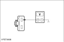
| C3: CHECK THE VOLTAGE SUPPLY OF THE FRONT LEFT-HAND TURN SIGNAL LAMP FOR OPEN CIRCUIT |
| | 1 Ignition switch in position II. |
| | 2 CHECK the turn signal lamps. |
| | 3 SWITCH ON the left-hand turn signal. |
| | 4 Measure the voltage between the left-hand headlamp, connector C1LF08, pin 8, circuit CLS21A (BU/GN), wiring harness side and ground. |
| | Is fluctuating battery voltage measured? Yes CHECK the left-hand headlamp and RENEW it as necessary. CHECK system operates correctly No |
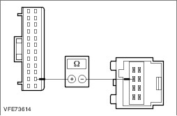
| C4: CHECK VOLTAGE SUPPLY OF THE FRONT LEFT-HAND TURN SIGNAL LAMP FOR OPEN CIRCUIT |
| | 1 Ignition switch in position 0. |
| | 2 Disconnect Smart Junction Box from connector C1BP02A. |
| | 3 Measure the resistance between the Smart Junction Box, connector C1BP02A, pin 19, circuit CLS21A (BU/GN), wiring harness side and the left-hand headlamp, connector C1LF08, pin 8, circuit CLS21A (BU/GN), wiring harness side. |
| | Is a resistance of less than 2 Ohms registered? Yes INSTALL A NEW Smart Junction Box. CHECK system operates correctly No LOCATE and RECTIFY the break in the circuit between the Smart Junction Box and the headlamp with the aid of the Wiring Diagrams. CHECK system operates correctly |
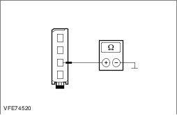
| C5: CHECK GROUND CONNECTION TO LEFT-HAND REAR LAMP ASSEMBLY FOR OPEN CIRCUIT |
| | 1 Ignition switch in position 0. |
| | 2 Disconnect Left-hand rear lamp assembly from connector C4LS18A. |
| | 3 Measure the resistance between the left-hand rear lamp assembly, connector C4LS18A, pin 3, circuit GD150C (BK/WH), wiring harness side and ground. |
| | Is a resistance of less than 2 Ohms registered? Yes No LOCATE and RECTIFY the break in the circuit between the rear lamp assembly and soldered connection SP549 with the aid of the Wiring Diagrams. CHECK system operates correctly |
| C6: CHECK VOLTAGE SUPPLY TO LEFT-HAND REAR LAMP ASSEMBLY FOR OPEN CIRCUIT |
| | 1 Ignition switch in position II. |
| | 2 SWITCH ON the left-hand turn signal. |
| | 3 Measure the voltage between the left-hand rear lamp assembly, connector C4LS18A, pin 4, circuit CLS23A (GY/OG), wiring harness side and ground. |
| | Is fluctuating battery voltage measured? Yes CHECK and if necessary RENEW the left-hand rear lamp assembly. CHECK system operates correctly No |
| C7: CHECK VOLTAGE SUPPLY TO LEFT-HAND REAR LAMP ASSEMBLY FOR OPEN CIRCUIT |
| | 1 Ignition switch in position 0. |
| | 2 Disconnect Smart Junction Box from connector C1BP02B. |
| | 3 Measure the resistance between the Smart Junction Box, connector C1BP02B, pin 36, circuit CLS23A (GY/OG), wiring harness side and the rear left lamp assembly, connector C4LS18A, pin 4, circuit CLS23A (GY/OG), wiring harness side. |
| | Is a resistance of less than 2 Ohms registered? Yes CHECK the Smart Junction Box with the aid of the WDS and RENEW it if required. CHECK system operates correctly No LOCATE and RECTIFY the break in the circuit between the Smart Junction Box and the rear lamp assembly with the aid of the Wiring Diagrams. CHECK system operates correctly |
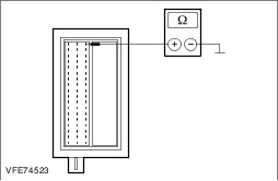
| C8: CHECK FUSE FA1/FA2 (25 A) (RJB) |
| | 1 Ignition switch in position 0. |
| | 2 Disconnect Fuse. |
| | 3 CHECK Fuse. |
| | Is the fuse OK.? Yes No - LHD: RENEW fuse FA1 (25 A) (RJB). CHECK system operates correctly If the fuse blows again, LOCATE and RECTIFY the short to ground using the Wiring Diagrams. CHECK system operates correctly - RHD: RENEW fuse FA2 (25 A) (RJB). CHECK system operates correctly If the fuse blows again, LOCATE and RECTIFY the short to ground using the Wiring Diagrams. CHECK system operates correctly |
| C9: CHECK THE VOLTAGE SUPPLY TO FUSE FA1/FA2 (25 A) (RJB) FOR OPEN CIRCUIT |
| | 1 Connect Fuse. |
| | 2 Ignition switch in position II. |
| | 3 Measure the voltage between fuse: - LHD: FA1 (25 A) (RJB) and ground.
- RHD: FA2 (25 A) (RJB) and ground.
|
| | Does the meter display battery voltage? Yes No - LHD: LOCATE and RECTIFY the break in the voltage supply of fuse FA1 (25 A) (RJB) with the aid of the Wiring Diagrams. CHECK system operates correctly - RHD: LOCATE and RECTIFY the break in the voltage supply of fuse FA2 (25 A) (RJB) with the aid of the Wiring Diagrams. CHECK system operates correctly |
| C10: CHECK THE VOLTAGE SUPPLY OF THE LEFT-HAND DOOR CONTROL MODULE FOR OPEN CIRCUIT |
| | 1 Ignition switch in position 0. |
| | 2 Disconnect Door control module, left-hand side from connector C5PL01A. |
| | 3 Ignition switch in position II. |
| | 4 Measure the voltage between the door control module, left-hand side, connector C5PL01A, pin 2, circuit SBR01A (RD), wiring harness side and ground. |
| | Does the meter display battery voltage? Yes No - LHD: LOCATE and RECTIFY the break in the circuit between the door control module and fuse FA1 (25 A) (RJB) with the aid of the Wiring Diagrams. CHECK system operates correctly - RHD: LOCATE and RECTIFY the break in the circuit between the door control module and fuse FA2 (25 A) (RJB) with the aid of the Wiring Diagrams. CHECK system operates correctly |
| C11: CHECK THE GROUND CONNECTION OF THE LEFT-HAND DOOR CONTROL MODULE FOR OPEN CIRCUIT |
| | 1 Ignition switch in position 0. |
| | 2 Measure the resistance between the left-hand door control module, connector C5PL01A, pin 13, circuit GD134H (BK/VT), wiring harness side and ground. |
| | Is a resistance of less than 2 Ohms registered? Yes No LOCATE and RECTIFY the break in the circuit between the door control module and soldered connection SP386 with the aid of the Wiring Diagrams. CHECK system operates correctly |
| C12: CHECK THE VOLTAGE SUPPLY TO THE INTEGRATED TURN SIGNAL LAMP IN THE LEFT-HAND EXTERIOR MIRROR FOR OPEN CIRCUIT |
| | 1 Connect Left-hand door control module to connector C5PL01A. |
| | 2 Disconnect Left-hand integrated turn signal lamp from connector C5PM26A. |
| | 3 Ignition switch in position II. |
| | 4 SWITCH ON the left-hand turn signal. |
| | 5 Measure the voltage between the integrated turn signal lamp, left-hand exterior mirror, connector C5PM26A, pin 7, circuit CLS22A (GN/BN), wiring harness side and ground. |
| | Is fluctuating battery voltage measured? Yes No |
| C13: CHECK THE GROUND SUPPLY TO THE INTEGRATED TURN SIGNAL LAMP IN THE LEFT-HAND EXTERIOR MIRROR FOR OPEN CIRCUIT |
| | 1 Ignition switch in position 0. |
| | 2 Measure the resistance between the integrated turn signal lamp, left-hand exterior mirror, connector C5PM26A, pin 6, circuit RPM05A (VT/GN), wiring harness side and ground. |
| | Is a resistance of less than 2 Ohms registered? Yes RENEW the integrated turn signal lamp in the exterior mirror CHECK system operates correctly No |
| C14: CHECK THE GROUND CONNECTION BETWEEN THE DOOR CONTROL MODULE AND THE INTEGRATED TURN SIGNAL LAMP IN THE LEFT-HAND EXTERIOR MIRROR FOR OPEN CIRCUIT |
| | 1 Disconnect Door control module, left-hand side from connector C5PL01B. |
| | 2 Measure the resistance between the integrated turn signal lamp, left-hand exterior mirror, connector C5PM26A, pin 6, circuit RPM05A (VT/GN), wiring harness side and the door control module, left-hand side, connector C5PL01B, pin 23, circuit RPM05A (VT/GN), wiring harness side. |
| | Is a resistance of less than 2 Ohms registered? Yes RENEW the door control module. CHECK system operates correctly No LOCATE and RECTIFY the break in the circuit between the integrated turn signal lamp in the exterior mirror and the door control module using the Wiring Diagrams. CHECK system operates correctly |
| C15: CHECK THE VOLTAGE SUPPLY TO THE INTEGRATED TURN SIGNAL LAMP IN THE LEFT-HAND EXTERIOR MIRROR FOR OPEN CIRCUIT |
| | 1 Ignition switch in position 0. |
| | 2 Disconnect Left-hand door control module from connector C5PL01B. |
| | 3 Measure the resistance between the left-hand door control module, connector C5PL01B, pin 11, circuit CLS22A (GN/BN), wiring harness side and the integrated turn signal lamp, left-hand exterior mirror, connector C5PM26A, pin 7, circuit CLS22A (GN/BN), wiring harness side. |
| | Is a resistance of less than 2 ohms registered? Yes CHECK and if necessary RENEW the door control module. CHECK system operates correctly If the concern persists:
REFER to: Kommunikations-Netzwerk (418-00, Diagnosis and Testing).
No LOCATE and RECTIFY the break in the circuit between the door control module and the integrated turn signal lamp in the exterior mirror using the Wiring Diagrams. CHECK system operates correctly |
| C16: CHECK THE GROUND CONNECTION TO THE RIGHT-HAND HEADLAMP FOR OPEN CIRCUIT |
| | 1 Ignition switch in position 0. |
| | 2 Measure the resistance between the right-hand headlamp, connector C1LF09, pin 7, circuit GD132M (BK/VT), wiring harness side and ground. |
| | 3 Measure the resistance between the right-hand headlamp, connector C1LF09, pin 9, circuit GD132X (BK/VT), wiring harness side and ground. |
| | Is a resistance of less than 2 Ohm measured in both cases? Yes No LOCATE and RECTIFY the break in the circuit between the headlamp and soldered connection SP380 using the wiring diagrams. CHECK system operates correctly |
| C17: CHECK THE VOLTAGE SUPPLY TO THE FRONT RIGHT-HAND TURN SIGNAL LAMP FOR OPEN CIRCUIT |
| | 1 Ignition switch in position II. |
| | 2 SWITCH ON the right-hand turn signal. |
| | 3 Measure the voltage between the right-hand headlamp, connector C1LF09, pin 8, circuit CLS25A (YE/VT), wiring harness side and ground. |
| | Is fluctuating battery voltage measured? Yes CHECK and if necessary RENEW the headlamp. CHECK system operates correctly No |
| C18: CHECK THE VOLTAGE SUPPLY TO THE FRONT RIGHT-HAND TURN SIGNAL LAMP FOR OPEN CIRCUIT |
| | 1 Ignition switch in position 0. |
| | 2 Disconnect Smart Junction Box from connector C1BP02A. |
| | 3 Measure the resistance between the Smart Junction Box, connector C1BP02A, pin 1, circuit CLS25A (YE/VT), wiring harness side and the right-hand headlamp, connector C1LF09, pin 8, circuit CLS25A (YE/VT), wiring harness side. |
| | Is a resistance of less than 2 Ohms registered? Yes INSTALL A NEW Smart Junction Box. CHECK system operates correctly No LOCATE and RECTIFY the break in the circuit between the headlamp and the Smart Junction Box with the aid of the Wiring Diagrams. CHECK system operates correctly |
| C19: CHECK THE GROUND CONNECTION TO THE RIGHT-HAND REAR LAMP ASSEMBLY FOR OPEN CIRCUIT |
| | 1 Ignition switch in position 0. |
| | 2 Disconnect Right-hand rear lamp assembly from connector C4LS19A. |
| | 3 Measure the resistance between the right-hand rear lamp assembly, connector C4LS19A, pin 3, circuit GD152A (BK/BU), wiring harness side and ground. |
| | Is a resistance of less than 2 Ohms registered? Yes No LOCATE and RECTIFY the break in the circuit between the rear lamp assembly and soldered connection SP600 with the aid of the Wiring Diagrams. CHECK system operates correctly |
| C20: CHECK VOLTAGE SUPPLY TO RIGHT-HAND REAR LAMP ASSEMBLY FOR OPEN CIRCUIT |
| | 1 Ignition switch in position II. |
| | 2 SWITCH ON the right-hand turn signal. |
| | 3 Measure the voltage between the right-hand rear lamp assembly, connector C4LS19A, pin 4, circuit CLS27A (GN/OG), wiring harness side and ground. |
| | Is fluctuating battery voltage measured? Yes CHECK and if necessary RENEW the right-hand rear lamp assembly. CHECK system operates correctly No |
| C21: CHECK VOLTAGE SUPPLY TO RIGHT-HAND REAR LAMP ASSEMBLY FOR OPEN CIRCUIT |
| | 1 Ignition switch in position 0. |
| | 2 Disconnect Smart Junction Box from connector C1BP02B. |
| | 3 Measure the resistance between the Smart Junction Box, connector C1BP02B, pin 18, circuit CLS27A (GN/OG), wiring harness side and the rear right lamp assembly, connector C4LS19A, pin 4, circuit CLS27A (GN/OG), wiring harness side. |
| | Is a resistance of less than 2 Ohms registered? Yes INSTALL A NEW Smart Junction Box. CHECK system operates correctly No LOCATE and RECTIFY the break in the circuit between the rear lamp assembly and the Smart Junction Box with the aid of the Wiring Diagrams. CHECK system operates correctly |
| C22: CHECK FUSE FA2/FA1 (25 A) (RJB) |
| | 1 Ignition switch in position 0. |
| | 2 Disconnect Fuse. |
| | 3 CHECK Fuse. |
| | Is the fuse OK.? Yes No - LHD: RENEW fuse FA2 (25 A) (RJB) and CHECK the operation of the system. If the fuse blows again, LOCATE and RECTIFY the short to ground using the Wiring Diagrams. CHECK system operates correctly - RHD: RENEW fuse FA1 (25 A) (RJB) and CHECK the operation of the system. If the fuse blows again, LOCATE and RECTIFY the short to ground using the Wiring Diagrams. CHECK system operates correctly |
| C23: CHECK THE VOLTAGE SUPPLY TO FUSE FA2/FA1 (25 A) (RJB) FOR OPEN CIRCUIT |
| | 1 Connect Fuse. |
| | 2 Ignition switch in position II. |
| | 3 Measure the voltage between fuse: - LHD: FA2 (25 A) (RJB) and ground.
- RHD: FA1 (25 A) (RJB) and ground.
|
| | Does the meter display battery voltage? Yes No - LHD: LOCATE and RECTIFY the break in the voltage supply of fuse FA2 (25 A) (RJB) with the aid of the Wiring Diagrams. CHECK system operates correctly - RHD: LOCATE and RECTIFY the break in the voltage supply of fuse FA1 (25 A) (RJB) with the aid of the Wiring Diagrams. CHECK system operates correctly |
| C24: CHECK THE VOLTAGE SUPPLY TO THE RIGHT-HAND DOOR CONTROL MODULE FOR OPEN CIRCUIT |
| | 1 Ignition switch in position 0. |
| | 2 Disconnect Right-hand door control module from connector C6PL01A. |
| | 3 Ignition switch in position II. |
| | 4 Measure the voltage between the door control module, right-hand side, connector C6PL01A, pin 2, circuit SBR02A (YE/RD), wiring harness side and ground. |
| | Does the meter display battery voltage? Yes No - LHD: LOCATE and RECTIFY the break in the circuit between the door control module and fuse FA2 (25 A) (RJB) with the aid of the Wiring Diagrams. CHECK system operates correctly - RHD: LOCATE and RECTIFY the break in the circuit between the door control module and fuse FA1 (25 A) (RJB) with the aid of the Wiring Diagrams. CHECK system operates correctly |
| C25: CHECK THE GROUND SUPPLY OF THE RIGHT-HAND DOOR CONTROL MODULE FOR OPEN CIRCUIT |
| | 1 Ignition switch in position 0. |
| | 2 Measure the voltage between the door control module, right-hand side, connector C6PL01A, pin 13, circuit GD140D (BK/GN), wiring harness side and ground. |
| | Is a resistance of less than 2 Ohms registered? Yes No LOCATE and RECTIFY the break in the circuit between the door control module and soldered connection SP392 with the aid of the Wiring Diagrams. CHECK system operates correctly |
| C26: CHECK THE VOLTAGE SUPPLY TO THE INTEGRATED TURN SIGNAL LAMP IN THE RIGHT-HAND EXTERIOR MIRROR FOR OPEN CIRCUIT |
| | 1 Connect Right-hand door control module to connector C6PL01A. |
| | 2 Disconnect Right-hand integrated turn signal lamp from connector C5PM31A. |
| | 3 Ignition switch in position II. |
| | 4 SWITCH ON the right-hand turn signal. |
| | 5 Measure the voltage between the integrated turn signal lamp, right-hand exterior mirror, connector C5PM31A, pin 7, circuit CLS26A (BU/GY), wiring harness side and ground. |
| | Is fluctuating battery voltage measured? Yes No |
| C27: CHECK THE GROUND SUPPLY TO THE INTEGRATED TURN SIGNAL LAMP IN THE RIGHT-HAND EXTERIOR MIRROR FOR OPEN CIRCUIT |
| | 1 Ignition switch in position 0. |
| | 2 Measure the resistance between the integrated turn signal lamp, right-hand exterior mirror, connector C5PM31A, pin 6, circuit RPM08A (GN/BU), wiring harness side and ground. |
| | Is a resistance of less than 2 Ohms registered? Yes RENEW the integrated turn signal lamp in the exterior mirror CHECK system operates correctly No |
| C28: CHECK THE GROUND CONNECTION BETWEEN THE RIGHT-HAND DOOR CONTROL MODULE AND THE INTEGRATED TURN SIGNAL LAMP IN THE RIGHT-HAND EXTERIOR MIRROR FOR OPEN CIRCUIT |
| | 1 Disconnect Door control module from connector C6PL01B. |
| | 2 Measure the resistance between the integrated turn signal lamp, right-hand exterior mirror, connector C5PM31A, pin 6, circuit RPM08A (GN/BU), wiring harness side and the door control module, right-hand side, connector C6PL01B, pin 23, circuit RPM08A (GN/BU), wiring harness side. |
| | Is a resistance of less than 2 Ohms registered? Yes RENEW the door control module. CHECK system operates correctly No LOCATE and RECTIFY the break in the circuit between the integrated turn signal lamp in the exterior mirror and the door control module using the Wiring Diagrams. CHECK system operates correctly |
| C29: CHECK THE VOLTAGE SUPPLY TO THE INTEGRATED TURN SIGNAL LAMP IN THE RIGHT-HAND EXTERIOR MIRROR FOR OPEN CIRCUIT |
| | 1 Ignition switch in position 0. |
| | 2 Disconnect Right-hand door control module from connector C6PL01B. |
| | 3 Measure the resistance between the right-hand door control module, connector C6PL01B, pin 11, circuit CLS26A (BU/GY), wiring harness side and the integrated turn signal lamp, right-hand exterior mirror, connector C5PM31A, pin 7, circuit CLS26A (BU/GY), wiring harness side. |
| | Is a resistance of less than 2 ohms registered? Yes CHECK and if necessary RENEW the door control module. CHECK system operates correctly If the concern persists:
REFER to: Kommunikations-Netzwerk (418-00, Diagnosis and Testing).
No LOCATE and RECTIFY the break in the circuit between the door control module and the integrated turn signal lamp in the exterior mirror using the Wiring Diagrams. CHECK system operates correctly |
| C30: CHECK FUSE F19 (60 A) (EJB) |
| | 1 Ignition switch in position 0. |
| | 2 Disconnect fuse F19 (60 A) (EJB). |
| | 3 CHECK fuse F19 (60 A) (EJB). |
| | Is the fuse OK.? Yes No RENEW fuse F19 (60 A) (EJB) and CHECK the operation of the system. If the fuse blows again, LOCATE and RECTIFY the short to ground using the Wiring Diagrams. CHECK system operates correctly |
| C31: CHECK THE VOLTAGE SUPPLY TO FUSE F19 (60 A) (EJB) FOR OPEN CIRCUIT |
| | 1 Connect fuse F19 (60 A) (EJB). |
| | 2 Ignition switch in position II. |
| | 3 Measure the voltage between fuse F19 (60 A) (EJB) and ground. |
| | Does the meter display battery voltage? Yes No LOCATE AND RECTIFY the break in the voltage supply of fuse F19 (60 A) (EJB) with the aid of the wiring diagrams. CHECK system operates correctly |
| C32: CHECK THE JOINT VOLTAGE SUPPLY OF THE INTEGRATED TURN SIGNAL LAMPS IN THE EXTERIOR MIRRORS FOR OPEN CIRCUIT |
| | 1 Measure the voltage between fuse FA1/FA2 (25 A) (RJB) and ground. |
| | Does the meter display battery voltage? Yes REFER to: Kommunikations-Netzwerk (418-00, Diagnosis and Testing). No LOCATE and RECTIFY the break in the circuits between fuse F19 (60 A) (EJB) and FA1/FA2 (25 A) (RJB) using the Wiring Diagrams. CHECK system operates correctly |