The locking system is available with a central locking function and a double locking function.
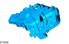
The systems consists of hard wired door latches, wired to the individual door control units (if equipped). The door latches are linked through the mid speed controller area network (CAN) bus to the central junction box (CJB).
On Vehicles with rear manual windows, there are no rear door control units intergrated into the rear door latches. The rear door latches are directly wired and controlled by the CJB.
The key position signal is sent from the driver door lock cylinder to the CJB. The CJB operates the lock or unlock relays, reversing the polarity of the door latch central locking motors.
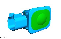
Liftgate latch release operation is controlled directly by the CJB.
The fuel filler door lock is wired in parallel with the driver door latch central locking motor.
2
-
Liftgate release switch
3
-
Radio frequency (RF) receiver
4
-
Remote keyless entry (RKE) module
5
-
Central junction box (CJB)
RKE systems use mechanical/electrical door latches individually controlled by the corresponding RKE module.
RKE modules send and receive commands between each other and the CJB using the central area network (CAN) bus.
When a key is turned in the door lock cylinder, a lock or unlock signal is sent to the associated RKE module. The RKE module sends a signal to the CJB. The CJB issues a signal to the remaining RKE modules, which in turn command the latches to operate.
RKE is achieved by the transmission of a coded RF signal from a transmitter contained in the vehicle key. The signal is received by the RF receiver located above the headliner in the vicinity of the overhead console. The received signal is passed onto the CJB where it is decoded. If the coded signal is valid, the CJB will issue a command on the CAN bus circuit to operate the door latches or liftgate release.
The signals received by the CJB from the RF antenna or the RKE modules is also used to arm and disarm the vehicle security systems, illuminate the interior lights and operate the global closing functions.
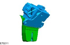
Liftgate Latch
Door latches have mechanical latch release with electric motor operated locking and double locking function.
When the door latch is locked, the exterior door handle is disengaged from the door latch.
Incorporated within the door latch is a door ajar switch. The door ajar switch monitors the latch position and supplies information to the RKE module. This information is sent to the CJB for use in warning systems, locking functions and alarm system.