| PINPOINT TEST A : REAR FOG LAMPS OR FRONT FOG LAMPS INOPERATIVE |
| TEST CONDITIONS | DETAILS/RESULTS/ACTIONS |
| A1: DETERMINE THE FAULT CONDITION |
| | 1 Ignition switch in position II. |
| | 2 SWITCH ON the dipped beam. |
| | 3 SWITCH ON the front and rear fog lamps. |
| | 4 CHECK fog lamps. |
| | Are the front fog lamps inoperative? Yes No |
| A2: CHECK FUSE F27 (CJB) |
| | 1 Ignition switch in position 0. |
| | 2 Disconnect Fuse F27 (20 A) (CJB). |
| | 3 CHECK fuse F27 (20 A) (CJB). |
| | Is the fuse OK.? Yes No RENEW fuse F27 (20 A) and CHECK the operation of the system. If the fuse blows again, LOCATE and RECTIFY the short to ground using the Wiring Diagrams. CHECK the operation of the system. |
| A3: CHECK THE VOLTAGE AT FUSE F27 (CJB) |
| | 1 Connect Fuse F27 (20 A) (CJB). |
| | 2 Ignition switch in position II. |
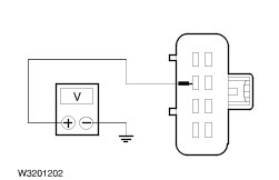
| | 3 Measure the voltage between fuse F27 (20 A) and ground. |
| | Does the meter display battery voltage? Yes No LOCATE AND RECTIFY the break in the voltage supply of fuse F27 (CJB) with the aid of the wiring diagrams. CHECK the operation of the system. |
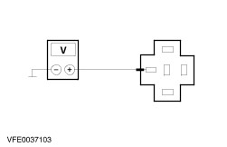
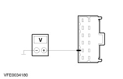
| A4: CHECK THE VOLTAGE AT THE FRONT FOG LAMP SWITCH |
| | 1 Ignition switch in position 0. |
| | 2 Disconnect front fog lamp switch from connector C532. |
| | 3 Ignition switch in position II. |
| | 4 SWITCH ON the dipped beam. |
| | 5 Measure the voltage between the front fog lamp switch, connector C532, pin 2, circuit 29S-LD10 (OG/GN), wiring harness side and ground. |
| | Does the meter display battery voltage? Yes No LOCATE and RECTIFY the break in the circuit between the front fog lamp switch and soldered connection S21 using the Wiring Diagrams. CHECK the operation of the system. |
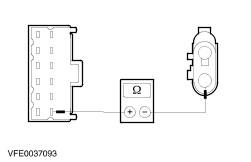
| A5: CHECK FRONT FOG LAMP SWITCH |
| | 1 Ignition switch in position 0. |
| | 2 SWITCH OFF the dipped beam. |
| | 3 Using a fused bridging cable (10 A) at the front fog lamp switch, connect between connector C532, pin 2, circuit 29S-LD10 (OG/GN) and pin 1, circuit 29S-LD8 (OG), wiring harness side. |
| | 4 Ignition switch in position II. |
| | 5 SWITCH ON the dipped beam. |
| | 6 CHECK the front fog lamps. |
| | Do the front fog lamps illuminate? Yes RENEW the front fog lamp switch. CHECK the operation of the system. No |
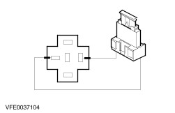
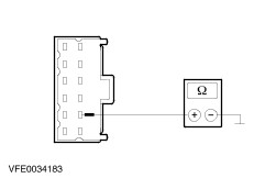
| A6: CHECK CIRCUIT 29S-LD8 (OG) FOR OPEN CIRCUIT (CONTROL CIRCUIT) |
| | 1 Ignition switch in position 0. |
| | 2 SWITCH OFF the dipped beam. |
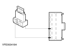
| | 3 Disconnect front fog lamp relay from socket C178. |
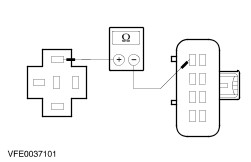
| | 4 Measure the resistance between the front fog lamp switch, connector C532, pin 1, circuit 29S-LD8 (OG), wiring harness side and the front fog lamp relay, socket C178, pin 2. |
| | Is the resistance less than 2 Ohm? Yes No LOCATE and RECTIFY the break in the circuit between the front fog lamp switch and the front fog lamp relay with the aid of the Wiring Diagrams. CHECK the operation of the system. |
| A7: CHECK GROUND CONNECTION AT FRONT FOG LAMP RELAY CIRCUIT 31-LD8 (BK)FOR OPEN CIRCUIT (CONTROL CIRCUIT) |
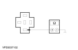
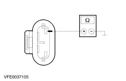
| | 1 Measure the resistance between the front fog lamp relay, socket C178, pin 1, circuit 31-LD8 (BK), wiring harness side and ground. |
| | Is the resistance less than 2 Ohm? Yes No LOCATE and RECTIFY the break in the circuit between the front fog lamp relay and soldered connection S145 using the wiring diagrams. CHECK the operation of the system. |
| A8: CHECK THE VOLTAGE SUPPLY TO FRONT FOG LAMP RELAY CIRCUIT 14-LD9 (VT/BK)FOR OPEN CIRCUIT (CONTROL CIRCUIT) |
| | 1 Measure the voltage between the front fog lamp relay, socket C178, pin 3, circuit 14-LD9 (VT/BK), wiring harness side and ground. |
| | Does the meter display battery voltage? Yes No LOCATE and RECTIFY the break in the circuit between the front fog lamp relay and fuse F27 (CJB) with the aid of the Wiring Diagrams. CHECK the operation of the system. |
| A9: CHECK FRONT FOG LAMP RELAY |
| | 1 Connect a fused jumper wire (20 A) to the front fog lamp relay, socket C178, pin 3, circuit 14-LD9 (VT/BK) and pin 5, circuit 14S-LD1 (VT/YE) and circuit 14S-LD21 (VT/YE). |
| | 2 Ignition switch in position II. |
| | 3 CHECK the front fog lamps. |
| | Do the front fog lamps illuminate? Yes RENEW the front fog lamp relay. CHECK the operation of the system. No LOCATE and RECTIFY the break in circuit 14S-LD1 (VT/YE), between the front fog lamp relay and soldered connection S82 using the Wiring Diagrams. CHECK the operation of the system. |
| A10: CHECK FUSE F29 (CJB) |
| | 1 Ignition switch in position 0. |
| | 2 Disconnect Fuse F29 (10 A) (CJB). |
| | 3 CHECK fuse F29 (10 A) (CJB). |
| | Is the fuse OK.? Yes No RENEW fuse F29 (10 A) and CHECK the operation of the system. If the fuse blows again, LOCATE and RECTIFY the short to ground using the Wiring Diagrams. CHECK the operation of the system. |
| A11: CHECK THE VOLTAGE AT FUSE F29 (CJB) |
| | 1 Connect Fuse F29 (10 A) (CJB). |
| | 2 Ignition switch in position II. |
| | 3 SWITCH ON the dipped beam. |
| | 4 Measure the voltage between fuse F29 (10 A) and ground. |
| | Does the meter display battery voltage? Yes No LOCATE and RECTIFY the break in the voltage supply to fuse F29 (CJB) using the Wiring Diagrams. CHECK the operation of the system. |
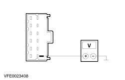
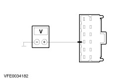
| A12: CHECK THE VOLTAGE AT THE HEATER CONTROL MODULE |
| | 1 Ignition switch in position 0. |
| | 2 Disconnect heater control module from connector C41. |
| | 3 Ignition switch in position II. |
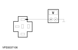
| | 4 Measure the voltage between the heater control module, connector C41, pin 1, circuit 14S-LD16B (VT), wiring harness side and ground. |
| | Does the meter display battery voltage? Yes No |
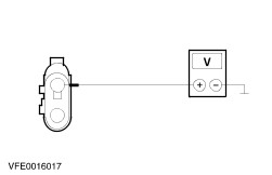
| A13: CHECK CIRCUIT 14S-LD22 (VT/WH) FOR OPEN CIRCUIT |
| | 1 Ignition switch in position 0. |
| | 2 Disconnect rear fog lamp diode from connector C185. |
| | 3 Ignition switch in position II. |
| | 4 Measure the voltage between the rear fog lamp diode, connector C185, pin 1, circuit 14S-LD22 (VT/WH), wiring harness side and ground. |
| | Does the meter display battery voltage? Yes No LOCATE and RECTIFY the break in the circuit between the rear fog lamp diode and fuse F29 (CJB) with the aid of the Wiring Diagrams. CHECK the operation of the system. |
| A14: CHECK CIRCUIT 14S-LD16(A/B) (VT) FOR OPEN CIRCUIT |
| | 1 Ignition switch in position 0. |
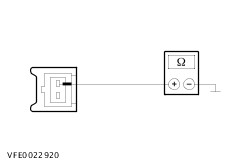
| | 2 Measure the resistance between the rear fog lamp diode, connector C185, pin 2, circuit 14S-LD16A (VT), wiring harness side and heater control module, connector C41, pin 1, circuit 14S-LD16B (VT). |
| | Is the resistance less than 2 Ohm? Yes RENEW the rear fog lamp diode. CHECK the operation of the system. No LOCATE and REPAIR the open circuit between the rear fog lamp diode and the heater control module using the Wiring Diagrams. CHECK the operation of the system. |
| A15: CHECK THE VOLTAGE AT THE HEATER CONTROL MODULE |
| | 1 Ignition switch in position II. |
| | 2 Measure the voltage between the heater control module, connector C41, pin 8, circuit 14-CA83(A) (VT/OG), wiring harness side and ground. |
| | Does the meter display battery voltage? Yes No LOCATE and RECTIFY the break in the circuit between the heater control module and soldered connection S6 using the Wiring Diagrams. CHECK the operation of the system. |
| A16: CHECK THE VOLTAGE AT THE HEATER CONTROL MODULE |
| | 1 Measure the voltage between the heater control module, connector C41, pin 9, circuit 29-CA83 (OG/GN), wiring harness side and ground. |
| | Does the meter display battery voltage? Yes No LOCATE and RECTIFY the break in the circuit between the heater control module and soldered connection S20 using the Wiring Diagrams. CHECK the operation of the system. |
| A17: CHECK THE GROUND CONNECTION OF THE HEATER CONTROL MODULE |
| | 1 Ignition switch in position 0. |
| | 2 Measure the resistance between the heater control module, connector C41, pin 2, circuit 91-CA83 (BK/RD), wiring harness side and ground. |
| | Is less than 2 Ohm measured? Yes No LOCATE and RECTIFY the break in the circuit between the heater control module and soldered connection S151 using the Wiring Diagrams. CHECK the operation of the system. |
| A18: CHECK THE HEATER CONTROL MODULE |
| | 1 Connect a fused jumper wire (10 A) to the heater control module, connector C41, between pin 9, circuit 29-CA83 (OG/GN) and pin 7, circuit 14S-LD6C (VT/YE), wiring harness side. |
| | Does the rear fog lamp illuminate? Yes CHECK and if necessary RENEW the heater control module. CHECK the operation of the system. No LOCATE and REPAIR the break in circuit 14S-LD6(C) (VT/YE), between the heater control module and soldered connection S163 using the Wiring Diagrams. CHECK the operation of the system. |