| PINPOINT TEST B : ONE OR MORE PARKING LAMPS, REAR LAMPS OR LICENSE PLATE LAMPS IS INOPERATIVE |
| TEST CONDITIONS | DETAILS/RESULTS/ACTIONS |
| B1: DETERMINE THE CONDITIONS UNDER WHICH THE FAULT OCCURS |
| | 1 Determine the fault condition. |
| | 2 Switch on SIDE LIGHTS. |
| | Is a left-hand parking lamp or license plate lamp inoperative? Yes - Front left-hand parking light, left-hand rear lamp and both license plate lamps inoperative (all other lamps OK): GO to B2. - Front left-hand parking lamp inoperative (all other lamps OK): GO to B4. - Left-hand rear lamp inoperative (all other lamps OK): GO to B10. - Both license plate lamps inoperative (all other lamps OK): LOCATE and RECTIFY the break in circuit 29S-LF23 (OG), between soldered connection S12 and soldered connection S121 using the Wiring Diagrams. CHECK the operation of the system. - Left-hand license plate lamp inoperative (all other lamps OK): GO to B16. No - Front right-hand parking lamp inoperative (all other lamps OK): GO to B7. - Right-hand rear lamp inoperative (all other lamps OK): GO to B13. - Front right-hand parking lamp and right-hand rear lamp inoperative (all other lamps OK): GO to B18. - Right-hand license plate lamp inoperative (all other lamps OK): GO to B20. |
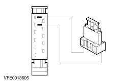
| B2: CHECK FUSE F6 (10 A) (CJB) |
| | 1 Ignition switch in position 0. |
| | 2 Disconnect fuse F6 (10 A) (CJB). |
| | 3 CHECK fuse F6 (10 A) (CJB). |
| | Is the fuse OK? Yes No RENEW fuse F6 (10 A) (CJB). If the fuse blows again, LOCATE and RECTIFY the short to ground using the Wiring Diagrams. CHECK the operation of the system. |
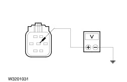
| B3: CHECK THE VOLTAGE AT FUSE F6 (10A) (CJB) |
| | 1 Connect fuse F6 (10 A) (CJB). |
| | 2 Ignition switch in position II. |
| | 3 Measure the voltage between fuse F6 (10 A) (CJB) and ground. |
| | Does the meter display battery voltage? Yes LOCATE and REPAIR the break in circuit 29S-DA1 (OG/YE) between fuse F6 (10A) (CJB) and soldered connection S12 using the Wiring Diagrams. CHECK the operation of the system. No RECTIFY the break in the voltage supply of fuse F6 (10A) (CJB) with the aid of the wiring diagrams. CHECK and INSTALL A NEW CJB if necessary. CHECK the operation of the system. |
| B4: CHECK LEFT-HAND HEADLAMP |
| | 1 Ignition switch in position II. |
| | 2 SWITCH ON dipped beam. |
| | 3 CHECK the dipped beam. |
| | Is the left-hand dipped beam working? Yes No |
| B5: CHECK VOLTAGE AT THE FRONT LEFT-HAND PARKING LAMP |
| | 1 Ignition switch in position 0. |
| | 2 Disconnect Left-hand headlamp from connector C65. |
| | 3 Switch on SIDE LIGHTS. |
| | 4 Test voltage between left-hand headlamp connector C65, pin 4, circuit 29S-LF7 (OG/BU), wiring harness side and ground. |
| | Does the meter display battery voltage? Yes CHECK and if necessary INSTALL A NEW headlamp. CHECK the operation of the system. No LOCATE and RECTIFY the break in the circuit between soldered connection S12 and the left-hand headlamp using the Wiring Diagrams. CHECK the operation of the system. |
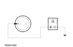
| B6: CHECK GROUND SUPPLY OF LEFT-HAND HEADLAMP FOR OPEN CIRCUIT |
| | 1 Ignition switch in position 0. |
| | 2 Disconnect Left-hand headlamp from connector C65. |
| | 3 Measure the resistance between left-hand headlamp, connector C65, pin 6, circuit 31-LE31 (BK), wiring harness side and ground. |
| | Is less than 2 Ohm measured? Yes CHECK and if necessary INSTALL A NEW headlamp. CHECK the operation of the system. No LOCATE and RECTIFY the break in the circuit between the left-hand headlamp and soldered connection S32 using the wiring diagrams. CHECK the operation of the system. |
| B7: CHECK THE RIGHT-HAND HEADLAMP |
| | 1 Ignition switch in position II. |
| | 2 SWITCH ON dipped beam. |
| | 3 CHECK the dipped beam. |
| | Is the right-hand dipped beam working? Yes No |
| B8: CHECK VOLTAGE AT THE FRONT RIGHT-HAND PARKING LAMP |
| | 1 Ignition switch in position 0. |
| | 2 Disconnect Right-hand headlamp from connector C66. |
| | 3 Switch on SIDE LIGHTS. |
| | 4 Measure the voltage between right-hand headlamp, connector C66, pin 4, circuit 29S-LF16 (OG/GN), wiring harness side and ground. |
| | Does the meter display battery voltage? Yes CHECK and if necessary INSTALL A NEW headlamp. CHECK the operation of the system. No LOCATE and RECTIFY the break in the circuit between fuse F7 (CJB) and the right headlamp using the wiring diagrams. CHECK the operation of the system. |
| B9: CHECK GROUND SUPPLY OF RIGHT-HAND HEADLAMP FOR OPEN CIRCUIT |
| | 1 Ignition switch in position 0. |
| | 2 Disconnect Right-hand headlamp from connector C66. |
| | 3 Measure the resistance between right-hand headlamp, connector C66, pin 6, circuit 31-LE30 (BK), wiring harness side and ground. |
| | Is less than 2 Ohm measured? Yes CHECK and if necessary INSTALL A NEW headlamp. CHECK the operation of the system. No LOCATE and RECTIFY the break in the circuit between the right-hand headlamp and soldered connection S4 using the wiring diagrams. CHECK the operation of the system. |
| B10: CHECK GROUND CONNECTION OF LEFT-HAND REAR LAMP ASSEMBLY |
| | 1 Ignition switch in position II. |
| | 2 Depress the BRAKE PEDAL and keep it depressed. |
| | 3 CHECK the left-hand stoplamp. |
| | Does the left-hand stoplamp operate? Yes No |
| B11: CHECK VOLTAGE SUPPLY TO LEFT-HAND REAR LAMP ASSEMBLY |
| | 1 Ignition switch in position 0. |
| | 2 Disconnect left-hand rear lamp assembly from connector C194. |
| | 3 Switch on SIDE LIGHTS. |
| | 4 Measure the voltage between the left-hand rear lamp assembly, connector C194, pin 2, circuit 29S-LF11A (OG/WH), wiring harness side and ground. |
| | Does the meter display battery voltage? Yes RENEW the left-hand rear lamp assembly. CHECK the operation of the system. No LOCATE and RECTIFY the break in the circuit between the left-hand rear lamp assembly and soldered connection S12 using the wiring diagrams. CHECK the operation of the system. |
| B12: CHECK GROUND CONNECTION TO LEFT-HAND REAR LAMP ASSEMBLY FOR OPEN CIRCUIT |
| | 1 Measure the resistance between the left-hand rear lamp assembly, connector C194, pin 3, circuit 31-LF23 (BK), wiring harness side and ground. |
| | Is less than 2 Ohm measured? Yes RENEW the left-hand rear lamp assembly. CHECK the operation of the system. No LOCATE and RECTIFY the break in the circuit between the left-hand rear lamp assembly and soldered connection S24 using the wiring diagrams. Check that the system operates properly. |
| B13: CHECK THE GROUND CONNECTION OF THE RIGHT-HAND REAR LAMP ASSEMBLY |
| | 1 Ignition switch in position II. |
| | 2 Depress the BRAKE PEDAL and keep it depressed. |
| | 3 CHECK the right-hand stoplamp. |
| | Does the right-hand stoplamp operate? Yes No |
| B14: CHECK VOLTAGE SUPPLY TO RIGHT-HAND REAR LAMP ASSEMBLY |
| | 1 Ignition switch in position 0. |
| | 2 Disconnect right-hand rear lamp assembly from connector C195. |
| | 3 Switch on SIDE LIGHTS. |
| | 4 Measure the voltage between the right-hand rear lamp assembly, connector C195, pin 2, circuit 29S-LF20 (OG), wiring harness side and ground. |
| | Does the meter display battery voltage? Yes RENEW the right-hand rear lamp assembly. CHECK the operation of the system. No LOCATE and RECTIFY the break in the circuit between the right-hand rear lamp assembly and fuse F7 (CJB) using the Wiring Diagrams. CHECK the operation of the system. |
| B15: CHECK GROUND CONNECTION TO RIGHT-HAND REAR LAMP ASSEMBLY FOR OPEN CIRCUIT |
| | 1 Measure the resistance between the right-hand rear lamp assembly, connector C195, pin 3, circuit 31-LF24 (BK), wiring harness side and ground. |
| | Is less than 2 Ohm measured? Yes RENEW the right-hand rear lamp assembly. CHECK the operation of the system. No LOCATE and RECTIFY the break in the circuit between the right-hand rear lamp assembly and soldered connection S73 using the Wiring Diagrams. Check that the system operates properly. |
| B16: CHECK VOLTAGE SUPPLY TO LEFT-HAND LICENSE PLATE LAMP |
| | 1 Ignition switch in position 0. |
| | 2 Disconnect left-hand license plate lamp from connector C128. |
| | 3 Switch on SIDE LIGHTS. |
| | 4 Measure the voltage between the left-hand license plate lamp, connector C128, pin 1, circuit 29S-LF21 (OG/BK) and ground. |
| | Does the meter display battery voltage? Yes No LOCATE and RECTIFY the break in the circuit between the left-hand license plate lamp and soldered connection S121 using the Wiring Diagrams. CHECK the operation of the system. |
| B17: CHECK GROUND SUPPLY OF LEFT-HAND LICENSE PLATE LAMP FOR OPEN CIRCUIT |
| | 1 Measure the resistance between the left-hand license plate lamp, connector C128, pin 2, circuit 31-LF21 (BK), wiring harness side and ground. |
| | Is less than 2 Ohm measured? Yes RENEW the license plate lamp. CHECK the operation of the system. No LOCATE and RECTIFY the break in the circuit between the left-hand license plate lamp and soldered connection S120 using the Wiring Diagrams. CHECK the operation of the system. |
| B18: CHECK FUSE F7 (10 A) (CJB) |
| | 1 Ignition switch in position 0. |
| | 2 Disconnect fuse F7 (10 A) (CJB). |
| | 3 CHECK fuse F7 (10 A) (CJB). |
| | Is the fuse OK? Yes CHECK and REPAIR the CJB, if necessary RENEW the CJB. CHECK the operation of the system. No RENEW fuse F7 (10 A) (CJB). CHECK the operation of the system. If the fuse fails again: GO to B19. |
| B19: CHECK CIRCUITS 29S-LF20 (OG) AND 29S-LF16 (OG/GN) FOR SHORT TO GROUND |
| | 1 Disconnect Right-hand headlamp from connector C66. |
| | 2 Disconnect right-hand rear lamp assembly from connector C195. |
| | 3 Measure the resistance between fuse F7 (10 A) (CJB) output side and ground. |
| | Is the resistance greater than 10000 Ohms? Yes Visually inspect the headlamp and lamp assembly, RENEW as necessary. CHECK the operation of the system. No LOCATE AND REPAIR the short to ground in the circuit(s) 29S-LF20 (OG) (between fuse F7 (CJB) and rear right-hand lamp assembly) or 29S-LF16 (OG/GN) (between fuse F7 (CJB) and right-hand headlamp) using the wiring diagrams. CHECK the operation of the system. |
| B20: CHECK VOLTAGE SUPPLY TO RIGHT-HAND LICENSE PLATE LAMP |
| | 1 Ignition switch in position 0. |
| | 2 Disconnect right-hand license plate lamp from connector C129. |
| | 3 Switch on SIDE LIGHTS. |
| | 4 Measure the voltage between right-hand license lamp, connector C129, pin 1, circuit 29S-LF22 (OG/BK), wiring harness side and ground. |
| | Does the meter display battery voltage? Yes No LOCATE and RECTIFY the break in the circuit between the right-hand license plate lamp and soldered connection S121 using the Wiring Diagrams. CHECK the operation of the system. |
| B21: CHECK GROUND SUPPLY OF RIGHT-HAND LICENSE PLATE LAMP FOR OPEN CIRCUIT |
| | 1 Measure the resistance between right-hand license lamp, connector C129, pin 2, circuit 31-LF22 (BK), wiring harness side and ground. |
| | Is the resistance less than 2 Ohm? Yes CHECK and RENEW the license plate lamp. CHECK the operation of the system. No LOCATE and RECTIFY the break in the circuit between the right-hand license plate lamp and soldered connection S120 using the Wiring Diagrams. CHECK the operation of the system. |