| PINPOINT TEST A : ELECTRIC BOOSTER HEATER INOPERATIVE / PARTLY INOPERATIVE |
NOTE:The electric booster heater only works when the engine is running, the battery is being charged by the generator, the ambient temperature is below 8°C and the coolant temperature has not yet exceeded 75°C. |
| TEST CONDITIONS | DETAILS/RESULTS/ACTIONS |
| A1: CHECK THE ELECTRIC BOOSTER HEATER |
| | 1 Ignition switch in position III. |
| | 2 Measure the current in circuits 15-RD23 (GN/BK) and 15-RD22 (GN/RD) at the electric booster heater using the clip-on ammeter. |
| | Is a current measured? Yes No |
| A2: CHECK 1ST STAGE OF ELECTRIC BOOSTER HEATER CIRCUIT |
| | 1 Measure the current in circuit 15-RD22 (GN/RD) at the electric booster heater using the clip-on ammeter. |
| | Is a current of more than 10 A measured? Yes No |
| A3: CHECK THE ELECTRIC BOOSTER HEATER GLOW PLUG |
| | 1 Ignition switch in position 0. |
| | 2 Measure the resistance between the electric booster heater, connector C965, circuit 15-RD22 (GN/RD), component side and electric booster heater housing. |
| | Is a resistance of less than 1.2 Ohm registered? Yes No RENEW the electric booster heater. CHECK the operation of the system. |
| A4: CHECK THE ELECTRIC BOOSTER HEATER GROUND CONNECTION |
| | 1 Measure the resistance between the electric booster heater, connector C968, circuit 31-RD22 (BK), component side and ground. |
| | Is a resistance of less than 1 Ohm registered? Yes No LOCATE and REPAIR the break in circuit 31-RD22 (BK) between the electric booster heater and ground connection G57 using the Wiring Diagrams. CHECK the operation of the system. |
| A5: CHECK THE SIGNAL FROM THE INTAKE AIR TEMPERATURE SENSOR |
NOTE:The intake air temperature sensor is integrated in the mass air flow sensor (engine management). |
| | 1 Connect the diagnostic tool. |
| | 2 Ignition switch in position II. |
| | 3 Check the intake air temperature signal using the WDS. |
| | Is the intake air temperature signal OK, i.e. is the indicated temperature value plausible? Yes Check the powertrain control module (PCM) and RENEW as necessary. CHECK the operation of the system. No |
| A6: CHECK FUSE F11 |
| | 1 Ignition switch in position 0. |
| | 2 CHECK fuse F11 (BJB). |
| | Is the fuse OK? Yes No RENEW fuse F11 (20 A). CHECK the operation of the system. If the fuse blows again, LOCATE and REPAIR the short to ground using the Wiring Diagrams. |
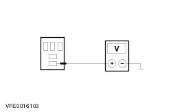
| A7: CHECK THE VOLTAGE AT FUSE F11 |
| | 1 Connect fuse F11 (BJB). |
| | 2 Measure the voltage between fuse F11 (20 A) and ground. |
| | Does the meter display battery voltage? Yes No REPAIR the voltage supply to fuse F11 using the Wiring Diagrams. CHECK the operation of the system. |
| A8: CHECK VOLTAGE AT GLOW PLUG HEATING RELAY, STAGE 1 |
| | 1 Disconnect glow plug heating relay, stage 1 C1013. |
| | 2 Measure the voltage between glow plug heating relay, stage 1, socket C1013, pin 3, circuit 30-RH24 (RD), wiring harness side and ground. |
| | Does the meter display battery voltage? Yes No LOCATE and REPAIR the break in circuit 30-RH24 (RD) between the glow plug heating relay, stage 1 and fuse F11 using the Wiring Diagrams. CHECK the operation of the system. |
| A9: CHECK CONTROL VOLTAGE AT GLOW PLUG HEATING RELAY, STAGE 1 |
| | 1 Ignition switch in position II. |
| | 2 Measure the voltage between glow plug heating relay, stage 1, socket C1013, pin 1, circuit 15-RH23 (GN/RD), wiring harness side and ground. |
| | Does the meter display battery voltage? Yes No LOCATE and REPAIR the break in circuit 15-RH23 (GN/RD) between glow plug heating relay, stage 1, and soldered connection S117 using the Wiring Diagrams. CHECK the operation of the system. |
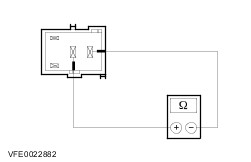
| A10: CHECK FOR OPEN CIRCUIT BETWEEN GLOW PLUG HEATING RELAY, STAGE 1, AND THE ELECTRIC BOOSTER HEATER. |
| | 1 Ignition switch in position 0. |
| | 2 Measure the resistance between glow plug heating relay, stage 1, socket C1013, pin 5, circuit 15-RH22 (GN/RD), wiring harness side and ground. |
| | Is a resistance of less than 1.2 Ohm registered? Yes No |
| A11: CHECK THE ELECTRIC BOOSTER HEATER |
| | 1 Measure the resistance between the electric booster heater, connector C965, circuit 15-RD22 (GN/RD), component side and ground. |
| | Is a resistance of less than 1.2 Ohm registered? Yes LOCATE and REPAIR the break in circuit 15-RD22 (GN/RD) between glow plug heating relay, stage 1, and the electric booster heater using the Wiring Diagrams. CHECK the operation of the system. No RENEW the electric booster heater. CHECK the operation of the system. |
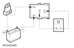
| A12: CHECK GLOW PLUG HEATING RELAY, STAGE 1 |
| | 1 Check glow plug heating relay 1, in accordance with the component test at the end of this section. |
| | Is the glow plug heating relay, stage 1 OK? Yes No RENEW glow plug heating relay, stage 1. CHECK the operation of the system. |
| A13: CHECK FOR OPEN CIRCUIT BETWEEN PCM AND GLOW PLUG HEATING RELAY, STAGE 1 - VEHICLES WITH 104 PIN EEC |
| | 1 Disconnect PCM C415. |
| | 2 Measure resistance between glow plug heating relay, stage 1, socket C1013, pin 2, circuit 31S-RH23 (BK/OG), wiring harness side and PCM, connector C415, pin 98, circuit 31S-RH23 (BK/OG), wiring harness side. |
| | Is a resistance of less than 2 Ohm registered? Yes CHECK the PCM and RENEW as necessary. CHECK the operation of the system. No LOCATE and REPAIR the break in circuit 31S-RH23 (BK/OG) between the PCM and the glow plug heating relay, stage 1, using the Wiring Diagrams. CHECK the operation of the system. |
| A14: CHECK FOR OPEN CIRCUIT BETWEEN PCM AND GLOW PLUG HEATING RELAY, STAGE 1 - VEHICLES WITH 121 PIN EEC |
| | 1 Disconnect PCM C414. |
| | 2 Measure resistance between glow plug heating relay, stage 1, socket C1013, pin 2, circuit 31S-RH23 (BK/OG), wiring harness side and PCM, connector C414, pin 61, circuit 31S-RH23 (BK/OG), wiring harness side. |
| | Is a resistance of less than 2 Ohm registered? Yes CHECK the PCM and RENEW as necessary. CHECK the operation of the system. No LOCATE and REPAIR the break in circuit 31S-RH23 (BK/OG) between the PCM and the glow plug heating relay, stage 1, using the Wiring Diagrams. CHECK the operation of the system. |
| A15: CHECK FUSE F18 |
| | 1 Ignition switch in position 0. |
| | 2 CHECK fuse F18 (BJB). |
| | Is the fuse OK? Yes No RENEW fuse F18 (40 A). CHECK the operation of the system. If the fuse blows again, LOCATE and REPAIR the short to ground using the Wiring Diagrams. |
| A16: CHECK THE VOLTAGE AT FUSE F18 |
| | 1 Connect fuse F18 (BJB). |
| | 2 Measure the voltage between fuse F18 (40 A) and ground. |
| | Does the meter display battery voltage? Yes No REPAIR the voltage supply to fuse F18 using the Wiring Diagrams. CHECK the operation of the system. |
| A17: CHECK VOLTAGE AT GLOW PLUG HEATING RELAY, STAGE 2 |
| | 1 Disconnect glow plug heating relay, stage 2 C1010. |
| | 2 Measure the voltage between glow plug heating relay, stage 2, socket C1010, pin 3, circuit 30-RH26 (RD), wiring harness side and ground. |
| | Does the meter display battery voltage? Yes No LOCATE and REPAIR the break in circuit 30-RH26 (RD) between the glow plug heating relay, stage 2 and fuse F18 using the Wiring Diagrams. CHECK the operation of the system. |
| A18: CHECK CONTROL VOLTAGE AT GLOW PLUG HEATING RELAY, STAGE 2 |
| | 1 Ignition switch in position II. |
| | 2 Measure the voltage between glow plug heating relay, stage 2, socket C1010, pin 1, circuit 15-RH25 (GN/BK), wiring harness side and ground. |
| | Does the meter display battery voltage? Yes No LOCATE and REPAIR the break in circuit 15-RH25 (GN/BK) between glow plug heating relay, stage 2, and soldered connection S117 using the Wiring Diagrams. CHECK the operation of the system. |
| A19: CHECK FOR OPEN CIRCUIT BETWEEN GLOW PLUG HEATING RELAY, STAGE 2, AND THE ELECTRIC BOOSTER HEATER. |
| | 1 Ignition switch in position 0. |
| | 2 Measure the resistance between glow plug heating relay, stage 2, socket C1010, pin 5, circuit 15-RH23 (GN/BK), wiring harness side and ground. |
| | Is a resistance of less than 0.8 Ohm registered? Yes No |
| A20: CHECK THE ELECTRIC BOOSTER HEATER |
| | 1 Disconnect electric booster heater C966. |
| | 2 Disconnect electric booster heater C967. |
| | 3 Measure the resistance between the electric booster heater, connector C966, circuit 15-RD23 (GN/BK), component side and ground. |
| | Is a resistance of less than 1.2 Ohm registered? Yes No RENEW the electric booster heater. CHECK the operation of the system. |
| A21: CHECK THE ELECTRIC BOOSTER HEATER |
| | 1 Measure the resistance between electric booster heater, connector C967, component side and ground. |
| | Is a resistance of less than 1.2 Ohm registered? Yes LOCATE and REPAIR the break in circuit 15-RD23 (GN/BK) between glow plug heating relay, stage 2 and the electric booster heater (or bridge at electric booster heater) using the Wiring Diagrams. CHECK the operation of the system. No RENEW the electric booster heater. CHECK the operation of the system. |
| A22: CHECK GLOW PLUG HEATING RELAY, STAGE 2 |
| | 1 Check glow plug heating relay 2, in accordance with the component test at the end of this section. |
| | Is the glow plug heating relay, stage 2 OK? Yes No RENEW glow plug heating relay, stage 2 CHECK the operation of the system. |
| A23: CHECK FOR OPEN CIRCUIT BETWEEN PCM AND GLOW PLUG HEATING RELAY, STAGE 2 - VEHICLES WITH 104 PIN EEC |
| | 1 Disconnect PCM C415. |
| | 2 Measure resistance between glow plug heating relay, stage 2, socket C1010, pin 2, circuit 31S-RH25 (BK/GN), wiring harness side and PCM, connector C415, pin 75, circuit 31S-RH25 (BK/GN), wiring harness side. |
| | Is a resistance of less than 2 Ohm registered? Yes CHECK the PCM and RENEW as necessary. CHECK the operation of the system. No LOCATE and REPAIR the break in circuit 31S-RH25 (BK/GN) between the PCM and the glow plug heating relay, stage 2, using the Wiring Diagrams. CHECK the operation of the system. |
| A24: CHECK FOR OPEN CIRCUIT BETWEEN PCM AND GLOW PLUG HEATING RELAY, STAGE 2 - VEHICLES WITH 121 PIN EEC |
| | 1 Disconnect PCM C414. |
| | 2 Measure resistance between glow plug heating relay, stage 2, socket C1010, pin 2, circuit 31S-RH25 (BK/GN), wiring harness side and PCM, connector C414, pin 62, circuit 31S-RH25 (BK/GN), wiring harness side. |
| | Is a resistance of less than 2 Ohm registered? Yes CHECK the PCM and RENEW as necessary. CHECK the operation of the system. No LOCATE and REPAIR the break in circuit 31S-RH25 (BK/GN) between the PCM and the glow plug heating relay, stage 2, using the Wiring Diagrams. CHECK the operation of the system. |