| Diagnosis and Testing Refer to Wiring Diagrams Section 412-02B, for schematic and connector information. Special Tool(s) | | Terminal Probe Kit 418-S035 | General Equipment Digital multimeter Worldwide Diagnostic System (WDS) Inspection and Checking - Visually CHECK for any obvious mechanical or electrical damage.
Visual Inspection | Mechanical | Electrical | - Coolant level
- Combustion air line
- Exhaust gas pipe
- Fuel line - booster heater
- Fuel tank fill level
| - Fuses
- Wiring harness
- Connectors
| - RECTIFY any obvious causes for a concern found during the visual inspection before performing any further tests. CHECK the operation of the system.
-
NOTE:Ensure that the fuel-fired booster heater is switched on during fault diagnosis with WDS. If necessary, bridge the ambient temperature thermo switch. If there is still cause for concern after the visual inspection, CARRY OUT fault diagnosis of the fuel fired booster heater at the powertrain control module (PCM) using the WDS tester and RECTIFY any displayed faults according to the fault description. CHECK the operation of the system. - If no fault is stored in the fault memory, PROCEED with the symptom chart according to the fault symptom.
- Following checking or elimination of the fault and after completion of operations, the fault memories of all vehicle modules must be READ OUT and any stored faults must be DELETED. READ OUT all fault memories again following a road test.
DTC index | DTC | Description | Action | | B1317 | Battery voltage too high, voltage greater than 16 V (excess voltage applied for more than 20 seconds) | CHECK battery,
REFER to: Battery (414-01 Battery, Mounting and Cables, Diagnosis and Testing).
| CHECK charging system,
REFER to: Generator (414-02 Generator and Regulator, Diagnosis and Testing).
| | B1318 | Battery voltage too low, voltage less than 10.2 V (undervoltage applied for more than 20 seconds) | CHECK battery,
REFER to: Battery (414-01 Battery, Mounting and Cables, Diagnosis and Testing).
| CHECK charging system,
REFER to: Generator (414-02 Generator and Regulator, Diagnosis and Testing).
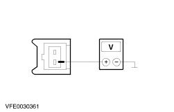
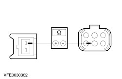
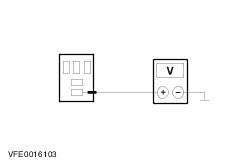
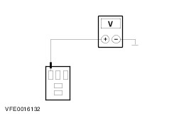
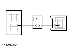
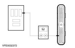
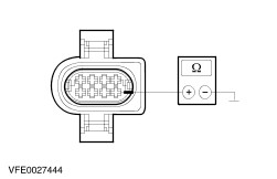
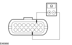
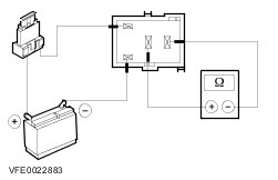
| | If battery and charging system are OK: | | - Vehicles with non-programmable fuel-fired booster heater: GO to Pinpoint Test A. | | - Vehicles with programmable fuel-fired booster heater: GO to Pinpoint Test B. | | B1342 | Control module defective | Renew control module | | B2449 | Glow plug circuit, short to ground | GO to Pinpoint Test E. | | B2450 | Glow plug circuit, open circuit | GO to Pinpoint Test E. | | B2451 | Auxiliary heater metering pump circuit, short to ground | GO to Pinpoint Test D. | | B2452 | Auxiliary heater metering pump circuit, open circuit | GO to Pinpoint Test D. | | B2453 | Combustion air blower motor circuit, short to ground | Check the combustion air blower motor according to the component check at the end of this section. | | B2454 | Combustion air blower motor circuit, open circuit | Check the combustion air blower motor according to the component check at the end of this section. | | B2455 | Combustion air blower motor speed outside the tolerance range | Check the combustion air blower motor according to the component check at the end of this section. | | B2456 | Temperature sensor circuit, short to ground | Check the temperature sensor according to the component check at the end of this section. | | B2457 | Temperature sensor circuit, open circuit | Check the temperature sensor according to the component check at the end of this section. | | B2458 | Overheating sensor circuit, short to ground | Check the overheating sensor according to the component check at the end of this section. | | B2459 | Overheating sensor circuit, open circuit | Check the overheating sensor according to the component check at the end of this section. | | B2460 | Flame sensor circuit, short to ground | Check the flame sensor according to the component check at the end of this section. | | B2461 | Flame sensor circuit, open circuit | Check the flame sensor according to the component check at the end of this section. | | B2462 | Flame extinguished during operation, attempt to restart failed | Check exhaust and combustion air pipes. | | Check fuel line of fuel fired booster heater. | | Check the additional heater metering pump fuel quantity according to the component check at the end of this section. | | If the components are OK, check the flame sensor according to the component check at the end of this section. | | B2463 | Overheating sensor triggered due to overheating | Check the cooling system: | | - Check the cooling system for leaks. | | - Check the cooling system for restrictions. | | - Bleed the cooling system. | | - Vehicles with programmable fuel-fired booster heater: Check the operation of the fuel-fired booster heater (coolant pump) | | If the cooling system is OK, check the temperature sensor and the overheating sensor according to the component check at the end of this section. | | B2464 | Safety period exceeded | Check exhaust and combustion air pipes. | | Check the additional heater metering pump fuel quantity according to the component check at the end of this section. | | B2465 | Operation lock, too many unsuccessful attempts at starting | Release the operation lock, delete the control module fault memory using WDS for this purpose. | | Check the additional heater metering pump fuel quantity according to the component check at the end of this section. | | B2466 | Operation lock, permissible number of overheating incidents exceeded | Release the operation lock, delete the control module fault memory using WDS for this purpose. | | Check the cooling system: | | - Check the cooling system for leaks. | | - Check the cooling system for restrictions. | | - Bleed the cooling system. | | - Vehicles with programmable fuel-fired booster heater: Check the operation of the fuel-fired booster heater (coolant pump) | | B2467 | Blower cooling time limit exceeded | Check exhaust and combustion air pipes. | | A temperature exceeding 70°C is measured by the flame sensor for longer than 240 seconds when the booster heater is switched on. | Check the flame sensor according to the component check at the end of this section. | Symptom Chart Symptom Chart | Symptom | Possible Sources | Action | | Fuel fired booster heater inoperative | * Fuse(s) * Circuit(s) * Ambient temperature thermo switch * Engine run relay * Central junction box * Fuel fired booster heater * Parking heater controls * Powertrain control module (PCM) | * Vehicles with non-programmable fuel-fired booster heater: GO to Pinpoint Test A. * Vehicles with programmable fuel-fired booster heater: GO to Pinpoint Test B. | | Fuel-fired booster heater/programmable fuel-fired booster heater not communicating with the diagnostic tester | * Fuel fired booster heater not switched on * Fuse(s) * Circuit(s) * Fuel fired booster heater /programmable fuel fired booster heater | * REFER to: (418-00 Module Communications Network) Communications Network - Vehicles Built Up To: 07/2006 (Diagnosis and Testing), Communications Network - Vehicles Built From: 07/2006 (Diagnosis and Testing). | | Blower motor inoperative with fuel-fired booster heater switched on - vehicles with programmable fuel-fired booster heater | * Fuse(s) * Circuit(s) * Blower relay, parking heater * Control module | * | | Auxiliary heater metering pump inoperative | * Circuit(s) * Auxiliary heater metering pump | * | | Glow plug inoperative | * Circuit(s) * Glow plug | * | | Fuel-fired booster heater (coolant pump) inoperative - vehicles with programmable fuel-fired booster heater | * Circuit(s) * Fuel-fired booster heater - coolant pump | * | Pinpoint Tests | PINPOINT TEST A : FUEL FIRED BOOSTER HEATER INOPERATIVE | NOTE:The fuel fired booster heater only works when the engine is running, the battery is being charged by the generator, the ambient temperature is below 8°C and the coolant temperature has not yet exceeded 75°C. | | TEST CONDITIONS | DETAILS/RESULTS/ACTIONS | | A1: CHECK FUSE F11 | | | 1 Ignition switch in position 0. | | | 2 CHECK fuse F11 (BJB). | | | Is the fuse OK? Yes No RENEW fuse F11 (20 A). CHECK the operation of the system. If the fuse blows again, LOCATE and REPAIR the short to ground using the Wiring Diagrams. | | A2: CHECK THE VOLTAGE AT FUSE F11 | | | 1 Connect fuse F11 (BJB). | | | 2 Measure the voltage between fuse F11 (20 A) and ground. | | | Does the meter display battery voltage? Yes No REPAIR the voltage supply to fuse F11 using the Wiring Diagrams. CHECK the operation of the system. | | A3: CHECK FUSE F34 | | | 1 CHECK fuse F34 (CJB). | | | Is the fuse OK? Yes No RENEW fuse F34 (7.5 A). CHECK the operation of the system. If the fuse blows again, LOCATE and REPAIR the short to ground using the Wiring Diagrams. | | A4: CHECK THE VOLTAGE AT FUSE F34 | | | 1 Connect fuse F34 (CJB). | | | 2 Ignition switch in position II. | | | 3 Measure the voltage between fuse F34 (7.5 A) and ground. | | | Does the meter display battery voltage? Yes No REPAIR the voltage supply to fuse F34 using the Wiring Diagrams. CHECK the operation of the system. | | A5: CHECK VOLTAGE AT FUEL FIRED BOOSTER HEATER | | | 1 Ignition switch in position 0. | | | 2 Disconnect fuel fired booster heater C878. | | | 3 Measure the voltage between the fuel fired booster heater, connector C878, pin 1, circuit 30-RD18 (RD), wiring harness side and ground. | | | Does the meter display battery voltage? Yes No LOCATE and REPAIR the break in circuit 30-RD18 (RD) between the fuel fired booster heater and soldered connection F11 using the Wiring Diagrams. CHECK the operation of the system. | | A6: CHECK VOLTAGE AT FUEL FIRED BOOSTER HEATER | | | 1 Ignition switch in position II. | | | 2 Measure the voltage between the fuel fired booster heater, connector C878, pin 4, circuit 15-RD18 (GN/RD), wiring harness side and ground. | | | Does the meter display battery voltage? Yes No LOCATE and REPAIR the break in circuit 15-RD18 (GN/RD) between the fuel fired booster heater and soldered connection S117 using the Wiring Diagrams. CHECK the operation of the system. | | A7: CHECK CONTROL VOLTAGE AT FUEL FIRED BOOSTER HEATER | | | 1 Cool the ambient temperature thermo switch to a temperature of 8°C or less using a suitable medium. | | | 2 Ignition switch in position III. 3 Run the engine at idle speed. | | | NOTE:The charge warning indicator must no longer illuminate. 4 Measure the voltage between the fuel fired booster heater, connector C878, pin 5, circuit 64S-RD18 (BU/WH), wiring harness side and ground. | | | Does the meter display battery voltage? Yes No | | A8: CHECK GROUND CONNECTION OF FUEL FIRED BOOSTER HEATER | | | 1 Ignition switch in position 0. | | | 2 Measure the resistance between the fuel fired booster heater, connector C878, pin 2, circuit 31-RD18 (BK), wiring harness side and ground. | | | Is a resistance of less than 2 Ohm registered? Yes CHECK the fuel fired booster heater and RENEW if necessary. CHECK the operation of the system. No LOCATE and REPAIR the break in circuit 31-RD18 (BK) between the fuel fired booster heater and soldered connection S121 using the Wiring Diagrams. CHECK the operation of the system. | | A9: CHECK VOLTAGE AT AMBIENT TEMPERATURE THERMO SWITCH | | | 1 Ignition switch in position 0. | | | 2 Disconnect ambient temperature thermo switch C875. | | | 3 Ignition switch in position III. 4 Run the engine at idle speed. | | | NOTE:The charge warning indicator must no longer illuminate. 5 Measure the voltage between the ambient temperature thermo switch, connector C875, pin 1, circuit 64-RD18 (BU/WH), wiring harness side and ground. | | | Does the meter display battery voltage? Yes No | | A10: CHECK FOR OPEN CIRCUIT BETWEEN THE AMBIENT TEMPERATURE THERMO SWITCH AND THE FUEL FIRED BOOSTER HEATER. | | | 1 Ignition switch in position 0. | | | 2 Measure the resistance between the ambient temperature thermo switch, connector C875, pin 2, circuit 64S-RD18 (BU/WH), wiring harness side and the fuel fired booster heater, connector C878, pin 5, circuit 64S-RD18 (BU/WH), wiring harness side. | | | Is a resistance of less than 2 Ohm registered? Yes RENEW the ambient temperature thermo switch. CHECK the operation of the system. No LOCATE and REPAIR the break in circuit 64S-RD18 (BU/WH) between the ambient temperature thermo switch and the fuel fired booster heater using the Wiring Diagrams. CHECK the operation of the system. | | A11: CHECK VOLTAGE AT ENGINE RUN RELAY | | | 1 Ignition switch in position 0. | | | 2 Disconnect engine run relay C1024 (CJB). | | | 3 Ignition switch in position II. | | | 4 Measure the voltage between the engine run relay, socket C1024, pin 3, wiring harness side and ground. | | | Does the meter display battery voltage? Yes No CHECK central junction box and RENEW if necessary. CHECK the operation of the system. | | A12: CHECK CONTROL VOLTAGE AT ENGINE RUN RELAY | | | 1 Measure the voltage between the engine run relay, socket C1024, pin 2, wiring harness side and ground. | | | Does the meter display battery voltage? Yes No CHECK central junction box and RENEW if necessary. CHECK the operation of the system. | | A13: CHECK FOR OPEN CIRCUIT BETWEEN THE ENGINE RUN RELAY AND THE AMBIENT TEMPERATURE THERMO SWITCH | | | 1 Ignition switch in position 0. | | | 2 Measure the resistance between the engine run relay, socket C1024, pin 5, wiring harness side and the ambient temperature thermo switch, connector C875, pin 1, circuit 64-RD18 (BU/WH), wiring harness side. | | | Is a resistance of less than 2 Ohm registered? Yes No | | A14: CHECK FOR OPEN CIRCUIT BETWEEN THE CJB AND THE AMBIENT TEMPERATURE THERMO SWITCH | | | 1 Disconnect connector C14 from CJB. | | | 2 Measure the resistance between the CJB, connector C14, pin 6, circuit 64S-RD18 (BU/WH), wiring harness side and the ambient temperature thermo switch, connector C875, pin 1, circuit 64-RD18 (BU/WH), wiring harness side. | | | Is a resistance of less than 2 Ohm registered? Yes CHECK the CJB and RENEW as necessary. CHECK the operation of the system. No LOCATE and REPAIR the break in the circuit between the CJB and the ambient temperature thermo switch with the aid of the Wiring Diagrams. CHECK the operation of the system. | | A15: CHECK THE ENGINE RUN RELAY | | | 1 Check the engine run relay according to the component check at the end of this section. | | | Is the engine run relay OK? Yes Vehicles with a 1.8L (90 PS) diesel engine: GO to A16. Vehicles with a 1.8L (75 PS) diesel engine: GO to A18. No RENEW the engine run relay. CHECK the operation of the system. | | A16: CHECK THE CIRCUIT BETWEEN THE ENGINE RUN RELAY AND THE POWERTRAIN CONTROL MODULE (PCM) FOR OPEN CIRCUIT - VEHICLES WITH A 1.8L (90 PS) DIESEL ENGINE | | | 1 Disconnect PCM C414. | | | 2 Measure the resistance between engine run relay, socket C1024, pin 1, wiring harness side and PCM, connector C414, pin 23, circuit 31S-PA19 (BK/GN), wiring harness side. | | | Is a resistance of less than 2 Ohm registered? Yes CHECK the PCM and RENEW as necessary. CHECK the operation of the system. No | | A17: CHECK THE CIRCUIT BETWEEN THE CJB AND THE PCM FOR CONTINUITY. | | | 1 Disconnect connector C10 from CJB. | | | 2 Measure the resistance between the CJB, connector C10, pin 3, circuit 31S-PA19 (BK/GN), wiring harness side and the PCM, connector C414, pin 23, circuit 31S-PA19 (BK/GN), wiring harness side. | | | Is a resistance of less than 2 Ohm registered? Yes CHECK the CJB and RENEW as necessary. CHECK the operation of the system. No LOCATE and REPAIR the open circuit between the CJB and the PCM with the aid of the Wiring Diagrams. CHECK the operation of the system. | | A18: CHECK THE CIRCUIT BETWEEN THE ENGINE RUN RELAY AND THE POWERTRAIN CONTROL MODULE (PCM) FOR OPEN CIRCUIT - VEHICLES WITH A 1.8L (75 PS) DIESEL ENGINE | | | 1 Disconnect PCM C415. | | | 2 Measure the resistance between engine run relay, socket C1024, pin 1, wiring harness side and PCM, connector C415, pin 6, circuit 31S-PA19 (BK/GN), wiring harness side. | | | Is a resistance of less than 2 Ohm registered? Yes CHECK the PCM and RENEW as necessary. CHECK the operation of the system. No | | A19: CHECK THE CIRCUIT BETWEEN THE CJB AND THE PCM FOR CONTINUITY. | | | 1 Disconnect connector C10 from CJB. | | | 2 Measure the resistance between the CJB, connector C10, pin 3, circuit 31S-PA19 (BK/GN), wiring harness side and the PCM, connector C415, pin 6, circuit 31S-PA19 (BK/GN), wiring harness side. | | | Is a resistance of less than 2 Ohm registered? Yes CHECK the CJB and RENEW as necessary. CHECK the operation of the system. No LOCATE and REPAIR the open circuit between the CJB and the PCM with the aid of the Wiring Diagrams. CHECK the operation of the system. | | PINPOINT TEST B : FUEL-FIRED BOOSTER HEATER INOPERATIVE - VEHICLES WITH PROGRAMMABLE FUEL-FIRED BOOSTER HEATER | NOTE:The fuel fired booster heater is equipped with an integrated undervoltage protection. This switches off the fuel fired booster heater when the supply voltage falls below 10 V for longer than 20 seconds. Before performing further checks, ensure that the vehicle battery is OK and that the charge state is sufficient. | NOTE:The fuel fired booster heater only works in booster heater mode if the engine is running, the battery is being charged by the generator, the ambient temperature is below 8°C and the coolant temperature has not yet exceeded 75°C. | | TEST CONDITIONS | DETAILS/RESULTS/ACTIONS | | B1: CHECK THE BOOSTER HEATER FUNCTION | | | 1 Ignition switch in position III. 2 Run the engine at idle speed. | | | NOTE:The charge warning indicator must no longer illuminate. 3 Cool the ambient temperature thermo switch to a temperature below 8° using a suitable medium. | | | Is the fuel fired booster heater working after the startup phase? Yes No | | B2: CHECK THE PARKING HEATER FUNCTION | | | 1 Ignition switch in position 0. | | | 2 Switch on the fuel-fired booster heater via the parking heater controls. | | | Is the fuel fired booster heater working after the startup phase? Yes No | | B3: CHECK FUSE F11 | | | 1 CHECK fuse F11 (BJB). | | | Is the fuse OK? Yes No RENEW fuse F11 (20 A). If the fuse blows again, LOCATE and REPAIR the short to ground using the Wiring Diagrams. CHECK the operation of the system. | | B4: CHECK THE VOLTAGE AT FUSE F11 | | | 1 Connect fuse F11 (BJB). | | | 2 Measure the voltage between fuse F11 (20 A) and ground. | | | Does the meter display battery voltage? Yes No REPAIR the voltage supply to fuse F11 using the Wiring Diagrams. CHECK the operation of the system. | | B5: CHECK THE VOLTAGE AT THE FUEL FIRED BOOSTER HEATER | | | 1 Disconnect Connector C501 from the fuel-fired booster heater. | | | 2 Measure the voltage between the fuel fired booster heater, connector C501, pin 1, circuit C30-RD18 (RD), wiring harness side and ground. | | | Does the meter display battery voltage? Yes No LOCATE and RECTIFY the break in circuit 30-RD18 (RD) between the fuel fired additional heater and fuse F11 with the aid of the Wiring Diagrams. CHECK the operation of the system. | | B6: CHECK FUSE FB | | | 1 Ignition switch in position 0. | | | 2 CHECK Fuse FB (auxiliary fuse box) (vehicles built from 02/2004: fuse holder 4). | | | Is the fuse OK? Yes No Renew fuse FB (5 A). If the fuse blows again, LOCATE and REPAIR the short to ground using the Wiring Diagrams. CHECK the operation of the system. | | B7: CHECK THE VOLTAGE AT FUSE FB | | | 1 Connect Fuse FB (auxiliary fuse box) (vehicles built from 02/2004: fuse holder 4). | | | 2 Measure the voltage between fuse FB (5 A) and ground. | | | Does the meter display battery voltage? Yes No REPAIR the voltage supply to fuse FB using the Wiring Diagrams. CHECK the operation of the system. | | B8: CHECK CONTROL VOLTAGE AT FUEL-FIRED BOOSTER HEATER | | | 1 Ignition switch in position 0. | | | 2 Switch on the fuel-fired booster heater via the parking heater controls. | | | 3 Measure the voltage between the fuel fired booster heater, connector C501, pin 7, circuit 8-FC14 (WH/BK), wiring harness side and ground. | | | Does the meter display battery voltage? Yes CHECK the fuel-fired booster heater using WDS and RECTIFY the fault(s) displayed according to the fault code table. CHECK the operation of the system.If no fault is stored: GO to B10. No | | B9: CHECK GROUND CONNECTION OF FUEL FIRED BOOSTER HEATER | | | 1 Switch off the fuel-fired booster heater via the parking heater control unit. | | | 2 Measure the resistance between the fuel fired booster heater, connector C501, pin 2, circuit 31-RD18A (BK), wiring harness side and ground. | | | Is a resistance of less than 2 Ohm registered? Yes CHECK the fuel-fired booster heater using WDS and RECTIFY the fault(s) displayed according to the fault code table. CHECK the operation of the system.If no fault is stored: GO to B10. No LOCATE and RECTIFY the break in the circuit between the fuel-fired additional heater and ground connection G37 with the aid of the Wiring Diagrams. CHECK the operation of the system. | | B10: CHECK THE TEMPERATURE SENSOR | | | 1 Check the temperature sensor according to the component check at the end of this section. | | | Is the temperature sensor OK? Yes RENEW the control module. CHECK the operation of the system. No RENEW the temperature sensor. CHECK the operation of the system. | | B11: CHECK THE VOLTAGE AT THE PARKING HEATER CONTROL UNIT | | | 1 Switch off the fuel-fired booster heater via the parking heater control unit. | | | 2 Disconnect Connector C505 from the parking heater control unit. | | | 3 Measure the voltage between the parking heater control unit, connector C505, pin 1, circuit 30-FC7 (RD), wiring harness side and ground. | | | Does the meter display battery voltage? Yes No LOCATE and REPAIR the break in the circuit between the parking heater control unit and fuse FB with the aid of the Wiring Diagrams. CHECK the operation of the system. | | B12: CHECK THE GROUND CONNECTION OF THE PARKING HEATER CONTROLS | | | 1 Measure the resistance between the parking heater control unit, connector C505, pin 3, circuit 31-FC7A (BK), wiring harness side and ground. | | | Is a resistance of less than 2 Ohm registered? Yes No LOCATE and REPAIR the break in the circuit between the parking heater control unit and ground connection G63 with the aid of the Wiring Diagrams. CHECK the operation of the system. | | B13: CHECK FOR OPEN CIRCUIT BETWEEN THE PARKING HEATER CONTROLS AND THE FUEL-FIRED BOOSTER HEATER | | | 1 Measure the resistance between the parking heater control unit, connector C505, pin 2, circuit 8-FC14 (WH/BK), wiring harness side and the fuel-fired booster heater, connector C501, pin 7, circuit 8-FC14 (WH/BK), wiring harness side. | | | Is a resistance of less than 2 Ohm registered? Yes No LOCATE and REPAIR the break in circuit 8-FC14 (WH/BK) between the parking heater control unit and the fuel fired booster heater with the aid of the Wiring Diagrams. CHECK the operation of the system. | | B14: CHECK FOR SHORT TO GROUND BETWEEN THE PARKING HEATER CONTROLS AND THE FUEL-FIRED BOOSTER HEATER | | | 1 Measure the resistance between the parking heater control unit, connector C505, pin 2, circuit 8-FC14 (WH/BK), wiring harness side and ground. | | | Is a resistance of more than 10,000 ohms measured? Yes RENEW the parking heater controls. CHECK the operation of the system. No LOCATE and REPAIR the short to ground in circuit 8-FC14 (WH/BK) between the parking heater control unit and the fuel fired booster heater with the aid of the Wiring Diagrams. CHECK the operation of the system. | | B15: CHECK VOLTAGE AT AMBIENT TEMPERATURE THERMO SWITCH | | | 1 Ignition switch in position 0. | | | 2 Disconnect ambient temperature thermo switch C875. | | | 3 Ignition switch in position III. 4 Run the engine at idle speed. | | | NOTE:The charge warning indicator must no longer illuminate. 5 Measure the voltage between the ambient temperature thermo switch, connector C875, pin 1, circuit 64-RD18 (BU/WH), wiring harness side and ground. | | | Does the meter display battery voltage? Yes No | | B16: CHECK FOR OPEN CIRCUIT BETWEEN THE AMBIENT TEMPERATURE THERMO SWITCH AND THE FUEL FIRED BOOSTER HEATER. | | | 1 Ignition switch in position 0. | | | 2 Measure the resistance between the ambient temperature thermo switch, connector C875, pin 2, circuit 64S-RD18 (BU/WH), wiring harness side and the fuel-fired booster heater, connector C501, pin 6, circuit 64S-RD18 (BU/WH), wiring harness side. | | | Is a resistance of less than 2 Ohm registered? Yes RENEW the ambient temperature thermo switch. CHECK the operation of the system. No LOCATE and REPAIR the break in circuit 64S-RD18 (BU/WH) between the ambient temperature thermo switch and the fuel fired booster heater using the Wiring Diagrams. CHECK the operation of the system. | | B17: CHECK VOLTAGE AT ENGINE RUN RELAY | | | 1 Ignition switch in position 0. | | | 2 Disconnect engine run relay C1024 (CJB). | | | 3 Ignition switch in position II. | | | 4 Measure the voltage between the engine run relay, socket C1024, pin 3, wiring harness side and ground. | | | Does the meter display battery voltage? Yes No CHECK central junction box and RENEW if necessary. CHECK the operation of the system. | | B18: CHECK CONTROL VOLTAGE AT ENGINE RUN RELAY | | | 1 Measure the voltage between the engine run relay, socket C1024, pin 2, wiring harness side and ground. | | | Does the meter display battery voltage? Yes No CHECK central junction box and RENEW if necessary. CHECK the operation of the system. | | B19: CHECK FOR OPEN CIRCUIT BETWEEN THE ENGINE RUN RELAY AND THE AMBIENT TEMPERATURE THERMO SWITCH | | | 1 Ignition switch in position 0. | | | 2 Measure the resistance between the engine run relay, socket C1024, pin 5, wiring harness side and the ambient temperature thermo switch, connector C875, pin 1, circuit 64-RD18 (BU/WH), wiring harness side. | | | Is a resistance of less than 2 Ohm registered? Yes No | | B20: CHECK FOR OPEN CIRCUIT BETWEEN THE CJB AND THE AMBIENT TEMPERATURE THERMO SWITCH | | | 1 Disconnect connector C14 from CJB. | | | 2 Measure the resistance between the CJB, connector C14, pin 6, circuit 64S-RD18 (BU/WH), wiring harness side and the ambient temperature thermo switch, connector C875, pin 1, circuit 64-RD18 (BU/WH), wiring harness side. | | | Is a resistance of less than 2 Ohm registered? Yes CHECK the CJB and RENEW as necessary. CHECK the operation of the system. No LOCATE and REPAIR the break in the circuit between the CJB and the ambient temperature thermo switch with the aid of the Wiring Diagrams. CHECK the operation of the system. | | B21: CHECK THE ENGINE RUN RELAY | | | 1 Check the engine run relay according to the component check at the end of this section. | | | Is the engine run relay OK? Yes Vehicles with a 1.8L (90 PS) diesel engine: GO to B22. Vehicles with a 1.8L (75 PS) diesel engine: GO to B24. No RENEW the engine run relay. CHECK the operation of the system. | | B22: CHECK THE CIRCUIT BETWEEN THE ENGINE RUN RELAY AND THE POWERTRAIN CONTROL MODULE (PCM) FOR OPEN CIRCUIT - VEHICLES WITH A 1.8L (90 PS) DIESEL ENGINE | | | 1 Disconnect PCM C414. | | | 2 Measure the resistance between engine run relay, socket C1024, pin 1, wiring harness side and PCM, connector C414, pin 23, circuit 31S-PA19 (BK/GN), wiring harness side. | | | Is a resistance of less than 2 Ohm registered? Yes CHECK the PCM and RENEW as necessary. CHECK the operation of the system. No | | B23: CHECK THE CIRCUIT BETWEEN THE CJB AND THE PCM FOR CONTINUITY. | | | 1 Disconnect connector C10 from CJB. | | | 2 Measure the resistance between the CJB, connector C10, pin 3, circuit 31S-PA19 (BK/GN), wiring harness side and the PCM, connector C414, pin 23, circuit 31S-PA19 (BK/GN), wiring harness side. | | | Is a resistance of less than 2 Ohm registered? Yes CHECK the CJB and RENEW as necessary. CHECK the operation of the system. No LOCATE and REPAIR the open circuit between the CJB and the PCM with the aid of the Wiring Diagrams. CHECK the operation of the system. | | B24: CHECK THE CIRCUIT BETWEEN THE ENGINE RUN RELAY AND THE POWERTRAIN CONTROL MODULE (PCM) FOR OPEN CIRCUIT - VEHICLES WITH A 1.8L (75 PS) DIESEL ENGINE | | | 1 Disconnect PCM C415. | | | 2 Measure the resistance between engine run relay, socket C1024, pin 1, wiring harness side and PCM, connector C415, pin 6, circuit 31S-PA19 (BK/GN), wiring harness side. | | | Is a resistance of less than 2 Ohm registered? Yes CHECK the PCM and RENEW as necessary. CHECK the operation of the system. No LOCATE and REPAIR the open circuit between the engine run relay and the PCM using the Wiring Diagrams. CHECK the operation of the system. | | B25: CHECK THE CIRCUIT BETWEEN THE CJB AND THE PCM FOR CONTINUITY. | | | 1 Disconnect connector C10 from CJB. | | | 2 Measure the resistance between the CJB, connector C10, pin 3, circuit 31S-PA19 (BK/GN), wiring harness side and the PCM, connector C415, pin 6, circuit 31S-PA19 (BK/GN), wiring harness side. | | | Is a resistance of less than 2 Ohm registered? Yes CHECK the CJB and RENEW as necessary. CHECK the operation of the system. No LOCATE and REPAIR the open circuit between the CJB and the PCM with the aid of the Wiring Diagrams. CHECK the operation of the system. | | PINPOINT TEST C : BLOWER MOTOR INOPERATIVE WHEN FUEL-FIRED BOOSTER HEATER SWITCHED ON - VEHICLES WITH PROGRAMMABLE FUEL-FIRED BOOSTER HEATER | NOTE:Before switching on the programmable fuel-fired booster heater the blower motor needs to be switched to its lowest setting via the blower switch. | | TEST CONDITIONS | DETAILS/RESULTS/ACTIONS | | C1: TEST FUSE FA | | | 1 Ignition switch in position 0. | | | 2 CHECK Fuse FB (auxiliary fuse box) (vehicles built from 02/2004: fuse holder 3). | | | Is the fuse OK? Yes No RENEW fuse FA (30 A). If the fuse blows again, LOCATE and RECTIFY the short circuit using the Wiring Diagrams. CHECK the operation of the system. | | C2: TEST VOLTAGE AT FUSE FA | | | 1 Connect Fuse FB (auxiliary fuse box) (vehicles built from 02/2004: fuse holder 3). | | | 2 Measure the voltage between fuse FA (30 A) and ground. | | | Does the meter display battery voltage? Yes No REPAIR the voltage supply to fuse FA using the Wiring Diagrams. CHECK the operation of the system. | | C3: CHECK THE BLOWER MOTOR CIRCUIT | | | 1 Disconnect Additional heater blower relay from socket C503. | | | 2 Use a fused test lead (30 A) at the additional heater blower relay, socket C503, to bridge pin 3 and pin 5, wiring harness side. | | | 3 Select the lowest blower switch setting. | | | Does the blower motor run at the selected speed? Yes No LOCATE and RECTIFY the break in the circuit between the additional heater blower relay and fuse FA with the aid of the Wiring Diagrams. CHECK the operation of the system. | | C4: CHECK THE CONTROL VOLTAGE AT THE ADDITIONAL HEATER BLOWER RELAY | | | 1 Switch on the fuel-fired booster heater via the parking heater controls. | | | NOTE:The control unit for the programmable fuel-fired booster heater does not connect a control voltage until the coolant temperature exceeds 30°C. 2 Measure the voltage between the additional heater blower relay, socket C503, pin 1, circuit 30S-FA23 (RD/BU), wiring harness side and ground. | | | Does the meter display battery voltage? Yes No | | C5: CHECK FOR OPEN CIRCUIT BETWEEN THE FUEL-FIRED BOOSTER HEATER AND THE ADDITIONAL HEATER BLOWER RELAY | CAUTION:In order to prevent damage to the control module, always wait for the run-on time of the fuel-fired booster heater to end before disconnecting. | | | 1 Switch off the fuel-fired booster heater via the parking heater control unit. | | | 2 Disconnect Connector C501 from the fuel-fired booster heater. | | | 3 Measure the resistance between the fuel-fired booster heater, connector C501, pin 3, circuit 30S-FA23 (RD/BU), wiring harness side and the additional heater blower relay, socket C503, pin 1, circuit 30S-FA23 (RD/BU), wiring harness side. | | | Is a resistance of less than 2 Ohm registered? Yes No LOCATE and REPAIR the break in circuit 30S-FA23 (RD/BU) between the fuel-fired booster heater and the additional heater blower relay with the aid of the Wiring Diagrams. CHECK the operation of the system. | | C6: CHECK THE CIRCUIT BETWEEN THE FUEL-FIRED BOOSTER HEATER AND THE ADDITIONAL HEATER BLOWER RELAY FOR A SHORT CIRCUIT TO GROUND | | | 1 Measure the resistance between the fuel-fired booster heater, connector C501, pin 3, circuit 30S-FA23 (RD/BU), wiring harness side and ground. | | | Is a resistance of more than 10,000 ohms measured? Yes CHECK the fuel-fired booster heater using WDS and RECTIFY the fault(s) displayed according to the fault code table. If no fault is stored: GO to C7. No LOCATE and REPAIR the short to ground in circuit 30S-FA23 (RD/BU) between the fuel-fired booster heater and the additional heater blower relay with the aid of the Wiring Diagrams. CHECK the operation of the system. | | C7: CHECK THE TEMPERATURE SENSOR | | | 1 Check the temperature sensor according to the component check at the end of this section. | | | Is the temperature sensor OK? Yes RENEW the control module. CHECK the operation of the system. No RENEW the temperature sensor. CHECK the operation of the system. | | C8: CHECK THE GROUND CONNECTION OF THE ADDITIONAL HEATER BLOWER RELAY | | | 1 Switch off the fuel-fired booster heater via the parking heater control unit. | | | 2 Measure the resistance between the additional heater blower relay, socket C503, pin 2, circuit 31-FA23 (BK), wiring harness side and ground. | | | Is a resistance of less than 2 Ohm registered? Yes RENEW the additional heater blower relay. CHECK the operation of the system. No LOCATE and RECTIFY the break in the circuit between the additional heater blower relay and ground connection G1 with the aid of the wiring diagrams. CHECK the operation of the system. | | PINPOINT TEST D : AUXILIARY HEATER METERING PUMP INOPERATIVE | | TEST CONDITIONS | DETAILS/RESULTS/ACTIONS | | D1: CHECK FOR OPEN CIRCUIT BETWEEN THE CONTROL MODULE AND THE AUXILIARY HEATER METERING PUMP | | | 1 Ignition switch in position 0. | | | 2 Disconnect Connector C501 from the fuel-fired booster heater. | | | 3 Disconnect Connector C502 from the additional heater metering pump. | | | 4 Measure the resistance between the fuel-fired booster heater, connector C501, pin 4, circuit 30S-FC14 (RD/BK), wiring harness side and the additional heater metering pump, socket C502, pin 2, circuit 30S-FC14 (RD/BK), wiring harness side. | | | Is a resistance of less than 2 Ohm registered? Yes GO to D2. RENEW the auxiliary heater metering pump. CHECK the operation of the system. No LOCATE and REPAIR the break in circuit 30S-FC14 (RD/BK) between the fuel-fired booster heater and the additional heater metering pump. CHECK the operation of the system. | | D2: CHECK THE GROUND CONNECTION OF THE ADDITIONAL HEATER METERING PUMP | | | 1 Measure the resistance between the additional heater metering pump, connector C502, pin 1, circuit 31-RD18B (BK), wiring harness side and ground. | | | Is a resistance of less than 2 Ohm registered? Yes No LOCATE and REPAIR the break in the circuit between the additional heater metering pump and soldered connection S121. CHECK the operation of the system. | | D3: CHECK THE CIRCUIT BETWEEN THE FUEL-FIRED BOOSTER HEATER AND THE ADDITIONAL HEATER METERING PUMP FOR A SHORT CIRCUIT TO VOLTAGE. | | | 1 Ignition switch in position II. | | | 2 Measure the voltage between the additional heater metering pump, connector C502, pin 2, circuit 30S-FC14 (RD/BK), wiring harness side and ground. | | | Is a voltage measured? Yes LOCATE and REPAIR the short to voltage in circuit 30S-FC14 (RD/BK) between the fuel-fired booster heater and the additional heater metering pump. CHECK the operation of the system. No | | D4: CHECK THE CIRCUIT BETWEEN THE FUEL-FIRED BOOSTER HEATER AND THE ADDITIONAL HEATER METERING PUMP FOR A SHORT CIRCUIT TO GROUND. | | | 1 Ignition switch in position 0. | | | 2 Measure the resistance between the additional heater metering pump, connector C502, pin 2, circuit 30S-FC14 (RD/BK), wiring harness side and ground. | | | Is a resistance of more than 10,000 ohms measured? Yes RENEW the auxiliary heater metering pump. CHECK the operation of the system.If the system is still inoperative, CHECK the wiring harness between the additional heater metering pump and the control unit for damage and REPAIR as necessary. If the wiring harness is OK, RENEW the control unit of the additional heater. No LOCATE and REPAIR the short to ground in circuit 30S-FC14 (RD/BK) between the fuel-fired booster heater and the additional heater metering pump. CHECK the operation of the system. | | PINPOINT TEST E : GLOW PLUG INOPERATIVE | CAUTION:Never apply 12 V to the glow plug. The glow plug is destroyed by voltages exceeding 8 V. | | TEST CONDITIONS | DETAILS/RESULTS/ACTIONS | | E1: CHECK THE GLOW PLUG. | | | 1 Disconnect Connector C1066 from control module. | | | 2 Measure the resistance at the control module, connector C1066, between pin 9 (WH) and pin 12 (BN), wiring harness side. | | | Is a resistance of less than 1 Ohms registered? Yes CHECK the wiring harness between the control module and the glow plug for damage and REPAIR if necessary. If the wiring harness is OK, RENEW the glow plug. CHECK the operation of the system. No | | E2: CHECK FOR OPEN CIRCUIT BETWEEN THE CONTROL MODULE AND THE GLOW PLUG. | | | 1 Disconnect Connectors C1071a and C1071b from the glow plug. | | | 2 Measure the resistance between the control module, connector C1066, pin 9 (WH), wiring harness side and the glow plug, connector C1071b (WH), wiring harness side. | | | 3 Measure the resistance between the control module, connector C1066, pin 12 (BN), wiring harness side and the glow plug, connector C1071a (BN), wiring harness side. | | | Is a resistance of less than 2 Ohms measured in both cases? Yes RENEW the glow plug. CHECK the operation of the system. No LOCATE and REPAIR the break in the relevant circuit between the control module and the glow plug using the Wiring Diagrams. CHECK the operation of the system. | | PINPOINT TEST F : FUEL-FIRED BOOSTER HEATER (COOLANT PUMP) INOPERATIVE - VEHICLES WITH PROGRAMMABLE FUEL-FIRED BOOSTER HEATER | | TEST CONDITIONS | DETAILS/RESULTS/ACTIONS | | F1: CHECK THE CIRCUIT BETWEEN THE FUEL-FIRED BOOSTER HEATER (COOLANT PUMP) AND THE CONTROL MODULE FOR SHORT CIRCUIT | | | 1 Disconnect Connector C1066 from control module. | | | 2 Disconnect Connector C1069 from the fuel-fired booster heater (coolant pump). | | | 3 Check the wiring harness between the control module, connector C1066 and the fuel-fired booster heater (coolant pump), connector C1069 for damage. | | | 4 Measure the resistance at the control module, connector C1066, between pin 10 (BN) and pin 11 (VT), wiring harness side. | | | Is the wiring harness undamaged and is a resistance greater than 10,000 Ohms measured? Yes No LOCATE and REPAIR the short circuit or damage in the circuit between the fuel-fired booster heater (coolant pump) and the control module. CHECK the operation of the system. | | F2: CHECK THE CIRCUIT BETWEEN THE FUEL-FIRED BOOSTER HEATER (COOLANT PUMP) AND THE CONTROL MODULE FOR OPEN CIRCUIT | | | 1 Measure the resistance between the control module, connector C1066, pin 10 (BN), wiring harness side and the fuel-fired booster heater (coolant pump), connector C1069 (BN), wiring harness side | | | 2 Measure the resistance between the control module, connector C1066, pin 11 (VT), wiring harness side and the fuel-fired booster heater (coolant pump), connector C1069 (VT), wiring harness side | | | Is a resistance of less than 2 Ohms measured in both cases? Yes RENEW the fuel-fired booster heater (coolant pump). CHECK the operation of the system. No LOCATE and REPAIR the break in the relevant circuit between the fuel-fired booster heater (coolant pump) and the control module. CHECK the operation of the system. | Component Tests Engine run relay - Check the normally open contact in the unswitched state.
- Measure the resistance at the relay, between pin 3 and pin 5, component side.
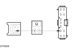
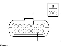
- Check the normally open contact in the switched state.
- Using a fused test cable (1 A), connect pin 2 of the relay, component side, to the battery positive terminal.
- Using a test cable, connect pin 1 of the relay, component side, to the battery negative terminal.
- Measure the resistance at the relay, between pin 3 and pin 5, component side.
- Is a resistance of less than 2 Ohm registered?
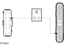
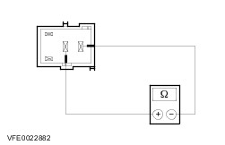
1. If yes, then the relay is OK. 2. If no, RENEW the relay. Combustion air blower motor CAUTION:Never apply 12 V to the combustion air blower motor. The combustion air blower motor is destroyed by voltages exceeding 8 V. - Combustion air blower motor speed not OK.
- CHECK the combustion air blower fanwheel and motor for ease of movement and soiling. Check for moisture, which can freeze at temperatures below 0° C. Ensure correct routing of the wiring harness. ELIMINATE stiffness or blockage, RENEW the combustion air blower motor if necessary.
- Combustion air blower motor, open/short circuit
- CHECK and REPAIR the combustion air blower motor for damage, RENEW the combustion air blower motor if necessary.
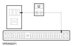
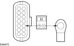
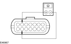
- Measure the resistance between the control module, connector C1066, pin 13 (BK), wiring harness side and the combustion air blower motor housing.
- Measure the resistance between the control module, connector C1066, pin 14 (BN), wiring harness side and the combustion air blower motor housing.
- Is a resistance greater than 2,000 Ohms measured in both cases?
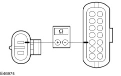
1. If yes, CHECK the combustion air blower fanwheel and motor for blockage. See above. 2. If no, RENEW the combustion air blower motor. Temperature sensor - CHECK both cables (BU) leading to the temperature sensor for damage and RENEW the temperature sensor if necessary.
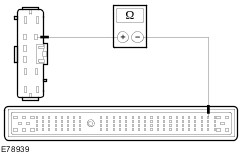
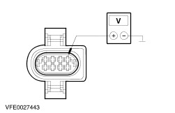
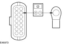
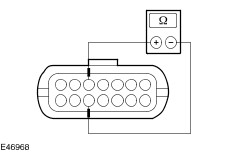
- Check the temperature sensor for a short to ground.
- Measure the resistance between the control module, connector C1066, pin 3 (BU), wiring harness side and the temperature sensor housing.
- Measure the resistance between the control module, connector C1066, pin 4 (BU), wiring harness side and the temperature sensor housing.
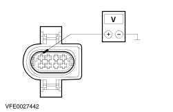
- Check the temperature sensor:
- Measure the resistance at the control module, connector C1066, between pin 3 and pin 4, wiring harness side.
- Compare the resistance value with the following table.
| Temperature | Resistance value | | 0 °C | 32.540 Ohm | | 10 °C | 19.870 Ohm | | 20 °C | 12.480 Ohm | | 30 °C | 8.060 Ohm | | 40 °C | 5.330Ohm | | 50 °C | 3.600 Ohm | | 60 °C | 2.480 Ohm | | 70 °C | 1.750 Ohm | | 80 °C | 1.250 Ohm | | 90 °C | 910 Ohm | | 100 °C | 670 Ohm | | 110 °C | 500 Ohm | | 120 °C | 380 Ohm | - Does the resistance measured correspond to the required value?
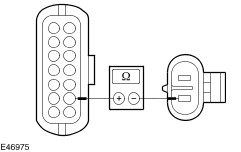
1. If yes, the temperature sensor is OK. 2. If no, RENEW the temperature sensor. Overheating sensor - CHECK both cables (RD) leading to the overheating sensor for damage and RENEW the overheating sensor if necessary.
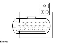
- Check the overheating sensor for a short to ground.
- Measure the resistance between the control module, connector C1066, pin 5 (RD), wiring harness side and the overheating sensor housing.
- Measure the resistance between the control module, connector C1066, pin 6 (RD), wiring harness side and the overheating sensor housing.
- Check the overheating sensor:
- Measure the resistance at the control module, connector C1066, between pin 5 and pin 6, wiring harness side.
- Compare the resistance value with the following table.
| Temperature | Resistance value | | 0 °C | 32.540 Ohm | | 10 °C | 19.870 Ohm | | 20 °C | 12.480 Ohm | | 30 °C | 8.060 Ohm | | 40 °C | 5.330Ohm | | 50 °C | 3.600 Ohm | | 60 °C | 2.480 Ohm | | 70 °C | 1.750 Ohm | | 80 °C | 1.250 Ohm | | 90 °C | 910 Ohm | | 100 °C | 670 Ohm | | 110 °C | 500 Ohm | | 120 °C | 380 Ohm | - Does the resistance measured correspond to the required value?
1. If yes, the overheating sensor is OK. 2. If no, RENEW the overheating sensor. Flame sensor - CHECK both cables leading to the flame sensor for damage and RENEW the flame sensor if necessary.
- Check the flame sensor for short to ground.
- Measure the resistance between the control module, connector C1066, pin 1 (BU), wiring harness side and the flame sensor housing.
- Measure the resistance between the control module, connector C1066, pin 2 (BN), wiring harness side and the flame sensor housing.
- Check the flame sensor:
- Measure the resistance at the control module, connector C1066, between pin 1 and pin 2, wiring harness side.
- Compare the resistance value with the following table.
| Temperature | Resistance value | | 0 °C | 1000 Ohm | | 10 °C | 1022 Ohm | | 20 °C | 1062 Ohm | | 30 °C | 1097 Ohm | | 50 °C | 1194 Ohm | | 80 °C | 1309 Ohm | | 90 °C | 1347 Ohm | | 100 °C | 1385 Ohm | | 130 °C | 1498 Ohm | | 150 °C | 1573 Ohm | | 200 °C | 1758 Ohm | | 250 °C | 1941 Ohm | | 300 °C | 2120 Ohm | | 350 °C | 2297 Ohm | | 400 °C | 2470 Ohm | - Does the resistance measured correspond to the required value?
1. If yes, the flame sensor is OK. 2. If no, RENEW the flame sensor. Check the additional heater metering pump fuel quantity NOTE:For the measurement, it must be ensured that the voltage at the booster heater is between 11 V and 13 V during the measurement, as otherwise the measurement result will be incorrect. Preparations for measuring the fuel quantity Disconnect the fuel line between the auxiliary heater metering pump and the heater. Lengthen the fuel line if necessary. Insert the free end of the fuel line into a suitable graduated vessel. Switch on the programmable fuel-fired booster heater via the parking heater controls or for vehicles with non-programmable fuel-fired booster heater, start the engine and run it at idle speed. (Note the switch-on conditions of the fuel-fired booster heater
REFER to: Auxiliary Heater (412-02B Auxiliary Heating, Description and Operation).
) If necessary, bridge the ambient temperature thermo switch. Fuel delivery begins 45 seconds after the fuel-fired booster heater is switched on. If the fuel escapes from the fuel line without air bubbles, switch off the fuel fired booster heater again and empty the graduated vessel. Measure the fuel quantity Switch on the programmable fuel-fired booster heater via the parking heater controls or for vehicles with non-programmable fuel-fired booster heater, start the engine and run it at idle speed. (Note the switch-on conditions of the fuel-fired booster heater
REFER to: Auxiliary Heater (412-02B Auxiliary Heating, Description and Operation).
) Fuel delivery begins after 45 seconds. NOTE:The end of the hose must be held at the height of the heater during the measurement. Fuel delivery ends automatically after approx. 90 seconds. Switch off the fuel fired booster heater. The fuel quantity delivered should be between 7.8 cm³ and 9.0 cm³. If the fuel quantity is outside this range check the additional heater fuel line and repair as required. Check that the connections are correct. Where fuel lines are joined by a length of hose, ensure that the ends of the fuel lines abut completely to prevent air bubbles from forming. If the booster heater fuel line is OK, renew the additional heater metering pump. |