| Disassembly and Assembly Special Tool(s) | | Preload Gauge 205-067 (15-041) | | | Remover, Bearing/Gear 205-310 (15-091) | | | Remover, Bearing/Gear 205-311 (15-092) | | | Adaptor for 204-028 308-111 (16-042A) | General Equipment Materials Name Specification Grease SAM-1C-911-A Disassembly CAUTION:Do not clamp the driveshaft in a vise. | | -
Before disassembling, mark the driveshaft mating tube and yoke as shown. | | | -
NOTE:Make a note of the position of the spacer. Detach the driveshaft yoke from the driveshaft center bearing. - Bend back the locking washer.
- Loosen the retaining bolt.
- Remove the spacer.
- Detach the driveshaft yoke from the driveshaft centre bearing spline.
- Discard the locking washer.
| | | -
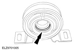
Using the special tools, remove the driveshaft center bearing. | Assembly | | -
Lubricate the mating faces of the driveshaft center bearing with grease. | | | -
Using the special tool, install the driveshaft center bearing. | | | -
NOTE:Install a new driveshaft yoke retaining bolt locking washer. NOTE:Do not fully tighten the driveshaft yoke retaining bolt at this stage. Install the locking washer and the bolt. | | | -
Align the driveshaft mating tube and yoke joint marks. | | | -
NOTE:The locating tang of the spacer must face towards the driveshaft center bearing. Install the spacer. | | | -
NOTE:The applied torque is dependant on the combined length of the ring spanner. NOTE:To obtain the correct torque, the ring spanner and the torque wrench must be in a straight line. - If using a wrench of 205 mm in length, apply a torque of 5 Nm.
- If using a wrench of 185 mm in length, apply a torque of 5.3 Nm.
- If using a ring wrench of 165 mm in length, apply a torque of 5.6 Nm.
| | | -
Lock the driveshaft yoke retaining bolt. - Bend the locking washer upwards.
| | |