| Removal and Installation Special Tool(s) | | Clamping Tool, Boot Retaining Clamp 204-169 (14-044) | | | Remover, Bearing/Gear 205-310 (15-091) | | | Remover, Bearing/Gear 205-311 (15-092) | | | Installer, Extension Housing Bushing/Oil Seal 308-046 (16-016) | Removal CAUTION:Support the halfshaft. The inner joint must not be bent more than 21 degrees. The outer joint must not be bent more than 45 degrees. | | -
Remove the halfshaft. For additional information, refer to: (205-04 Front Drive Halfshafts) Front Halfshaft LH (Removal and Installation), Front Halfshaft RH (Removal and Installation). | | | -
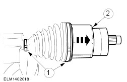
CAUTION:Use vise jaw protectors. Secure the halfshaft in a vise and detach the CV joint housing from the halfshaft. - Remove and discard the CV joint boot retaining clamps.
- Remove the CV joint housing and discard the grease filling.
| | | -
Remove and discard the spider circlip. | | | -
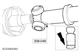
Using the special tools, remove the spider. - Discard the CV joint boot and insert.
| Installation CAUTION:Support the halfshaft. The inner joint must not be bent more than 21 degrees. The outer joint must not be bent more than 45 degrees. | | -
NOTE:Install a new CV joint boot retaining clamp. NOTE:Make sure that the inner cv joint boot clamp is loosely in place on the new joint boot. NOTE:Make sure that the inner end of the cv joint boot is seated in the sealing groove of the drive shaft. Install a new CV joint boot. | | | -
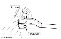
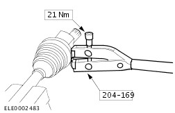
Using the special tool, install the CV joint boot inner retaining clamp. | | | -
CAUTION:Do not damage the CV joint bearings. Using the special tool, install the spider. | | | -
Install a new spider circlip. | | | -
CAUTION:The total amount of grease in the CV joint must not exceed 160 grams for 85 PS vehicles and 255 grams for 110/130 PS vehicles.
For additional information, refer to: Specifications (205-04 Front Drive Halfshafts, Specifications).
Apply grease to the CV joint. | | | -
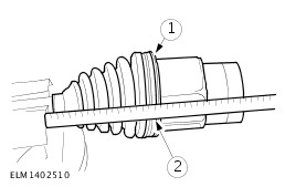
Attach the CV joint housing to the halfshaft. - Use a suitable screwdriver under the boot to allow air to escape.
- With the CV joint housing installed, measure the distance from the inner end of the CV joint boot to the outer end. The distance needs to be 90 mm.
| | | -
NOTE:Install a new CV joint boot retaining clamp. NOTE:Do not move the CV joint housing. Make sure that the CV joint boot is installed at the measured position. Using the special tool, install the CV joint boot outer retaining clamp. | | | -
Install the halfshaft. For additional information, refer to: (205-04 Front Drive Halfshafts) Front Halfshaft LH (Removal and Installation), Front Halfshaft RH (Removal and Installation). | | |