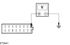
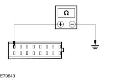
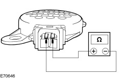
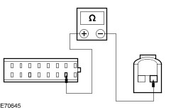
| Diagnosis and Testing Refer to Wiring Diagrams Section 413-13, for schematic and connector information. Worldwide Diagnostic System (WDS) Principles of Operation NOTE:The liftgate or rear doors must be closed for correct operation of the parking aid system. The parking aid system detects objects behind the vehicle when the vehicle reverse gear select input to the control module is enabled. The parking aid module does this by calculating the distance to an object by the use of four ultrasonic sensors mounted in the rear bumper. The sensors can detect objects approximately 1.8 meters to the rear of the vehicle, 50 centimeters to the rear-side of the vehicle, and 16 centimeters above the ground. An intermittent warning tone is generated from a speaker located behind the instrument panel. The interval between the tones decreases as the vehicle gets closer to an obstacle. When an object is detected within 25 centimeters of the sensors, the warning tone becomes continuous. The parking aid system will be disabled if a fault is detected in one of the four sensors, the parking aid speaker or the parking aid module. Inspection and Verification - Verify the customer concern.
- Visually inspect for obvious signs of electrical damage.
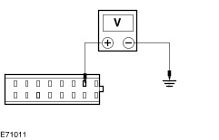
Visual Inspection Chart | Electrical | - Fuse(s)
- Wiring harness
- Electrical connector(s)
- Battery junction box (BJB)
- Central junction box (CJB)
- Relay(s)
- Parking aid sensor(s)
- Parking aid speaker
- Reversing lamps
- Reversing lamp switch
- Parking aid module
| - If an obvious cause for an observed or reported concern is found, correct the cause (if possible) before proceeding to the next step.
- Retrieve the diagnostic trouble codes (DTC)s and refer to the DTC Index Chart.
- If no DTCs are retrieved or there is no communication with the module, proceed to the Symptom Chart to continue diagnostics.
Diagnostic Trouble Codes (DTC) Index Chart DTC Index | DTC | Description | Possible Source | Action | | B4401 | Outer right parking aid sensor signal circuit open or short to ground | - Outer right parking aid sensor signal circuit.
- Parking aid sensor.
| GO to Pinpoint Test C. | | B4412 | Outer right parking aid sensor signal circuit short to power | - Outer right parking aid sensor signal circuit.
- Parking aid sensor.
| GO to Pinpoint Test C. | | B4496 | Concern with outer right parking aid sensor | - Outer right parking aid sensor.
| GO to Pinpoint Test C. | | B4601 | Inner right parking aid sensor signal circuit open or short to ground | - Inner right parking aid sensor signal circuit.
- Parking aid sensor.
| GO to Pinpoint Test D. | | B4612 | Inner right parking aid sensor signal circuit short to power | - Inner right parking aid sensor signal circuit.
- Parking aid sensor.
| GO to Pinpoint Test D. | | B4696 | Concern with inner right parking aid sensor | - Inner right parking aid sensor.
| GO to Pinpoint Test D. | | B4801 | Outer left parking aid sensor signal circuit open or short to ground | - Outer left parking aid sensor signal circuit.
- Parking aid sensor.
| GO to Pinpoint Test E. | | B4812 | Outer left parking aid sensor signal circuit short to power | - Outer left parking aid sensor signal circuit.
- Parking aid sensor.
| GO to Pinpoint Test E. | | B4896 | Concern with outer left parking aid sensor | - Outer left parking aid sensor.
| GO to Pinpoint Test E. | | B5001 | Inner left parking aid sensor signal circuit open or short to ground | - Inner left parking aid sensor signal circuit.
- Parking aid sensor.
| GO to Pinpoint Test F. | | B5012 | Inner left parking aid sensor signal circuit short to power | - Inner left parking aid sensor signal circuit.
- Parking aid sensor.
| GO to Pinpoint Test F. | | B5096 | Concern with inner left parking aid sensor | - Inner left parking aid sensor.
| GO to Pinpoint Test F. | | B5201 | Parking aid speaker circuit open circuit or short to ground | - Parking aid speaker.
- Parking aid module.
- Parking aid speaker circuit(s).
| GO to Pinpoint Test G. | | B5212 | Parking aid speaker circuit short to power | - Parking aid speaker.
- Parking aid module.
- Parking aid speaker circuit(s).
| GO to Pinpoint Test H. | | B5811 | Parking aid sensor power supply short to ground | - Outer right parking aid sensor circuit
- Inner right parking aid sensor circuit
- Outer left parking aid sensor circuit
- Inner left parking aid sensor circuit
| - For outer right parking aid sensor, GO to Pinpoint Test C.
- For inner right parking aid sensor circuit, GO to Pinpoint Test D.
- For outer left parking aid sensor circuit, GO to Pinpoint Test E.
- For inner left parking aid sensor circuit, GO to Pinpoint Test F.
| | U0049 | RAM Error | | INSTALL a new parking aid module.
REFER to: Parking Aid Module (413-13 Parking Aid, Removal and Installation).
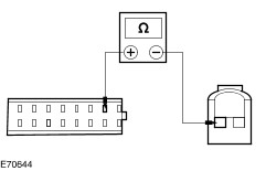
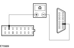
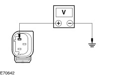
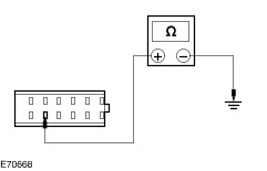
TEST the system for normal operation. | Symptom Chart | Symptom | Possible Sources | Action | | The parking aid is inoperative/does not operate correctly | * Fuse. * Circuit(s). * Parking aid module. | * | | No communication with the parking aid module | * DLC. * Circuit(s). * Parking aid module. | * | Pinpoint Tests NOTE:Use a digital multimeter for all electrical measurements. | PINPOINT TEST A : THE PARKING AID IS INOPERATIVE/DOES NOT OPERATE CORRECTLY | | TEST CONDITIONS | DETAILS/RESULTS/ACTIONS | | A1: CHECK THE PARKING AID MODULE FOR POWER | | | 1 Disconnect Parking aid module CMP01A. | | | 2 Measure the voltage between the parking aid module CMP01A pin 1, circuit SBP63C (WH/RD), harness side and ground. | | | Is the voltage greater than 10 volts? Yes No REPAIR circuit SBP63C (WH/RD). TEST the system for normal operation. | | A2: CHECK THE PARKING AID MODULE FOR GROUND | | | 1 Measure the resistance between the parking aid module CMP01A pin 8, circuit GD116F (BK/VT), harness side and ground. | | | Is the resistance less than 1 Ohm? Yes No REPAIR circuit GD116F (BK/VT). TEST the system for normal operation. | | A3: CHECK THE REVERSE LAMP FOR CORRECT OPERATION | | | 1 Select REVERSE. | | | 2 Check the reversing lamps for correct operation. | | | Do the reversing lamps illuminate? Yes No REFER to: Reversing Lamps (417-01 Exterior Lighting, Diagnosis and Testing). TEST the system for normal operation. | | A4: CHECK THE PARKING AID SPEAKER FOR CORRECT OPERATION | | | 1 Remove the parking aid speaker. | | | 2 Measure the resistance between the parking aid speaker CMP09 pin 1, and pin 2, component side. | | | Is the resistance 50 Ohms +/- 7.5 Ohms? Yes No INSTALL a new parking aid speaker. TEST the system for normal operation. | | A5: CHECK THE CIRCUIT CMP09A (BN/BU) FOR OPEN | | | 1 Disconnect Parking Aid Speaker CMP09. | | | 2 Measure the resistance between the parking aid module CMP01A pin 10, circuit CMP09A (BN/BU), harness side and the parking aid speaker CMP09 pin 1, circuit CMP09A (BN/BU), harness side. | | | Is the resistance less than 1 Ohm? Yes No REPAIR the circuit. TEST the system for normal operation. | | A6: CHECK THE CIRCUIT RMP09A (BU/GN) FOR OPEN | | | 1 Measure the resistance between the parking aid module CMP01A pin 2, circuit RMP09A (BU/GN), harness side and the parking aid speaker CMP09 pin 2, circuit RMP09A (BU/GN), harness side. | | | Is the resistance less than 1 Ohm? Yes INSTALL a new parking aid module.
REFER to: Parking Aid Module (413-13 Parking Aid, Removal and Installation).
TEST the system for normal operation. No REPAIR the circuit. TEST the system for normal operation. | | PINPOINT TEST B : NO COMMUNICATION WITH THE PARKING AID MODULE | | TEST CONDITIONS | DETAILS/RESULTS/ACTIONS | | B1: CHECK THAT WDS IS COMMUNICATING THROUGH THE DLC | | | 1 Select an alternative system to check the DLC. | | | Is WDS able to communicate with the selected alternative system? Yes No CHECK the DLC. For additional information, refer to the Wiring Diagrams. | | B2: CHECK CIRCUIT VDB07 (VT/OG) FOR OPEN CIRCUIT | | | 1 Disconnect Parking Aid Module CMP01A. | | | 2 Measure the resistance between the DLC pin 11 and the parking aid module CMP01A pin 7, circuit VDB07 (VT/OG), harness side. | | | Is the resistance less the 1 Ohm? Yes No REPAIR the circuit. TEST the system for normal operation. | | B3: CHECK CIRCUIT VDB06 (GY/OG) FOR OPEN CIRCUIT | | | 1 Measure the resistance between the DLC pin 3 and the parking aid module CMP01A pin 14, circuit VDB07 (GY/OG), harness side. | | | Is the resistance less the 1 Ohm? Yes INSTALL a new parking aid module.
REFER to: Parking Aid Module (413-13 Parking Aid, Removal and Installation).
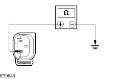
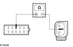
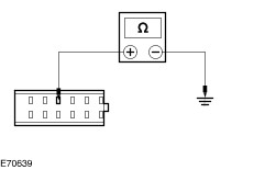
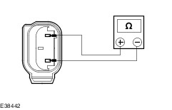
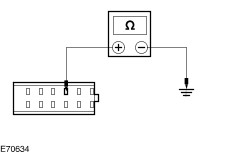
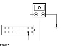
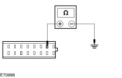
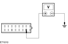
TEST the system for normal operation. No REPAIR the circuit. TEST the system for normal operation. | | PINPOINT TEST C : DTC B4401 : OUTER RIGHT PARKING AID SENSOR SIGNAL CIRCUIT OPEN OR SHORT TO GROUND. DTC B4412 : OUTER RIGHT SENSOR SIGNAL CIRCUIT SHORT TO POWER. B5811 : PARKING AID SENSOR POWER SUPPLY SHORT TO GROUND. | | TEST CONDITIONS | DETAILS/RESULTS/ACTIONS | | C1: CHECK THE OUTER RIGHT PARKING AID SENSOR FOR POWER | | | 1 Disconnect Outer Right Parking Aid Sensor CMP17. | | | 2 Measure the voltage between the outer right parking aid sensor CMP17 pin 1, circuit LMP07 (BU/WH), harness side and ground. | | | Is the voltage greater than 10 volts? Yes No REPAIR circuit LMP07 (BU/WH). TEST the system for normal operation. | | C2: CHECK THE CIRCUIT LMP07 (BU/WH) FOR SHORT TO GROUND | | | 1 Disconnect Parking Aid Module CMP01B. | | | 2 Measure the resistance between the parking aid module CMP01B pin 11, circuit LMP07 (BU/WH), harness side and ground. | | | Is the resistance greater than 10,000 Ohms? Yes No REPAIR the circuit. TEST the system for normal operation. | | C3: CHECK THE OUTER RIGHT PARKING AID SENSOR FOR GROUND | | | 1 Measure the resistance between the outer right parking aid sensor CMP17 pin 3, circuit RMP07 (GN/WH), harness side and ground. | | | Is the resistance less than 1 Ohm? Yes No REPAIR circuit RMP07 (GN/WH). TEST the system for normal operation. | | C4: CHECK CIRCUIT VMP17 (YE/OG) FOR OPEN | | | 1 Disconnect Parking Aid Module CMP01B. | | | 2 Measure the resistance between the parking aid module CMP01B pin 4, circuit VMP17 (YE/OG), harness side and the outer right parking aid sensor CMP17 pin 2, circuit circuit VMP17 (YE/OG), harness side. | | | Is the resistance less than 1 Ohm? Yes No REPAIR the circuit. TEST the system for normal operation. | | C5: CHECK THE OUTER RIGHT PARKING AID SENSOR FOR SHORT TO POWER | | | 1 Measure the voltage between the outer right parking aid sensor CMP17 pin 1, circuit LMP07 (BU/WH), harness side and ground. | | | Is the voltage less than 1 volt? Yes No REPAIR circuit LMP07 (WH/BU). TEST the system for normal operation. | | C6: CHECK CIRCUIT VMP17 (YE/OG) FOR SHORT TO GROUND | | | 1 Measure the resistance between the parking aid module CMP01B pin 4, circuit VMP17 (YE/OG), harness side and ground. | | | Is the resistance greater than 10,000 Ohms? Yes No REPAIR the circuit. TEST the system for normal operation. | | C7: CHECK THE PARKING AID SENSOR FOR SHORT BETWEEN PINS 1 AND 3 | | | 1 Measure the resistance of the parking aid sensor between pins 1, and 3, component side. | | | Is the resistance less than 1 Ohm? Yes INSTALL a new parking aid sensor(s). TEST the system for normal operation. No INSTALL a new parking aid module.
REFER to: Parking Aid Module (413-13 Parking Aid, Removal and Installation).
TEST the system for normal operation. | | PINPOINT TEST D : DTC B4601 : INNER RIGHT PARKING AID SENSOR SIGNAL CIRCUIT OPEN OR SHORT TO GROUND. DTC B4612 : INNER RIGHT PARKING AID SENSOR SIGNAL CIRCUIT SHORT TO POWER. B5811 : PARKING AID SENSOR POWER SUPPLY SHORT TO GROUND. | | TEST CONDITIONS | DETAILS/RESULTS/ACTIONS | | D1: CHECK THE INNER RIGHT PARKING AID SENSOR FOR POWER | | | 1 Disconnect Inner Right Parking Aid Sensor CMP16. | | | 2 Measure the voltage between the inner right parking aid sensor CMP16 pin 1, circuit LMP07 (BU/WH), harness side and ground. | | | Is the voltage greater than 10 volts? Yes No REPAIR circuit LMP07 (BU/WH). TEST the system for normal operation. | | D2: CHECK THE CIRCUIT LMP07 (BU/WH) FOR SHORT TO GROUND | | | 1 Disconnect Parking Aid Module CMP01B. | | | 2 Measure the resistance between the parking aid module CMP01B pin 11, circuit LMP07 (BU/WH), harness side and ground. | | | Is the resistance greater than 10,000 Ohms? Yes No REPAIR the circuit. TEST the system for normal operation. | | D3: CHECK THE INNER RIGHT PARKING AID SENSOR FOR GROUND | | | 1 Measure the resistance between the inner right parking aid sensor CMP16 pin 3, circuit RMP07 (GN/WH), harness side and ground. | | | Is the resistance less than 1 Ohm? Yes No REPAIR circuit RMP07 (GN/WH). TEST the system for normal operation. | | D4: CHECK CIRCUIT VMP16 (YE/GY) FOR OPEN | | | 1 Disconnect Parking Aid Module CMP01B. | | | 2 Measure the resistance between the parking aid module CMP01B pin 2, circuit VMP16 (YE/GY), harness side and the inner right parking aid sensor CMP16 pin 2, circuit VMP16 (YE/GY), harness side. | | | Is the resistance less than 1 Ohm? Yes No REPAIR the circuit. TEST the system for normal operation. | | D5: CHECK THE INNER RIGHT PARKING AID SENSOR FOR SHORT TO POWER | | | 1 Measure the voltage between the inner right parking aid sensor CMP16 pin 1, circuit LMP07 (BU/WH), harness side and ground. | | | Is the voltage less than 1 volt? Yes No REPAIR circuit LMP07 (WH/BU). TEST the system for normal operation. | | D6: CHECK CIRCUIT VMP16 (YE/GY) FOR SHORT TO GROUND | | | 1 Measure the resistance between the parking aid module C623 pin 2, circuit VMP16 (YE/GY), harness side and ground. | | | Is the resistance greater than 10,000 Ohms? Yes No REPAIR the circuit. TEST the system for normal operation. | | D7: CHECK THE PARKING AID SENSOR FOR SHORT BETWEEN PINS 1 AND 3 | | | 1 Measure the resistance of the parking aid sensor between pins 1, and 3, component side. | | | Is the resistance less than 1 Ohm? Yes INSTALL a new parking aid sensor(s). TEST the system for normal operation. No INSTALL a new parking aid module.
REFER to: Parking Aid Module (413-13 Parking Aid, Removal and Installation).
TEST the system for normal operation. | | PINPOINT TEST E : DTC B4801 : OUTER LEFT PARKING AID SENSOR SIGNAL CIRCUIT OPEN OR SHORT TO GROUND. DTC B4812 : OUTER LEFT PARKING AID SENSOR SIGNAL CIRCUIT SHORT TO POWER. B5811 : PARKING AID SENSOR POWER SUPPLY SHORT TO GROUND. | | TEST CONDITIONS | DETAILS/RESULTS/ACTIONS | | E1: CHECK THE OUTER LEFT PARKING AID SENSOR FOR POWER | | | 1 Disconnect Outer Left Parking Aid Sensor CMP15. | | | 2 Measure the voltage between the outer left parking aid sensor CMP15 pin 1, circuit LMP07 (BU/WH), harness side and ground. | | | Is the voltage greater than 10 volts? Yes No REPAIR circuit LMP07 (BU/WH). TEST the system for normal operation. | | E2: CHECK THE CIRCUIT LMP07 (BU/WH) FOR SHORT TO GROUND | | | 1 Disconnect Parking Aid Module CMP01B. | | | 2 Measure the resistance between the parking aid module CMP01B pin 11, circuit LMP07 (BU/WH), harness side and ground. | | | Is the resistance greater than 10,000 Ohms? Yes No REPAIR the circuit. TEST the system for normal operation. | | E3: CHECK THE OUTER LEFT PARKING AID SENSOR FOR GROUND | | | 1 Measure the resistance between the outer left parking aid sensor CMP15 pin 3, circuit RMP07 (GN/WH), harness side and ground. | | | Is the resistance less than 1 Ohm? Yes No REPAIR circuit RMP07 (GN/WH). TEST the system for normal operation. | | E4: CHECK CIRCUIT VMP15 (YE/GN) FOR OPEN | | | 1 Disconnect Parking Aid Module CMP01B. | | | 2 Measure the resistance between the parking aid module CMP01B pin 5, circuit VMP15 (YE/GN), harness side and the outer left parking aid sensor CMP15 pin 2, circuit VMP15 (YE/GN), harness side. | | | Is the resistance less than 1 Ohm? Yes No REPAIR the circuit. TEST the system for normal operation. | | E5: CHECK THE OUTER LEFT PARKING AID SENSOR FOR SHORT TO POWER | | | 1 Measure the voltage between the outer left parking aid sensor CMP15 pin 1, circuit LMP07 (BU/WH), harness side and ground. | | | Is the voltage less than 1 volt? Yes No REPAIR circuit LMP07 (WH/BU). TEST the system for normal operation. | | E6: CHECK CIRCUIT VMP15 (YE/GN) FOR SHORT TO GROUND | | | 1 Measure the resistance between the parking aid module CMP01B pin 5, circuit VMP15 (YE/GN), harness side and ground. | | | Is the resistance greater than 10,000 Ohms? Yes No REPAIR the circuit. TEST the system for normal operation. | | E7: CHECK THE PARKING AID SENSOR FOR SHORT BETWEEN PINS 1 AND 3 | | | 1 Measure the resistance of the parking aid sensor between pins 1, and 3, component side. | | | Is the resistance less than 1 Ohm? Yes INSTALL a new parking aid sensor(s). TEST the system for normal operation. No INSTALL a new parking aid module.
REFER to: Parking Aid Module (413-13 Parking Aid, Removal and Installation).
TEST the system for normal operation. | | PINPOINT TEST F : DTC B5001 : INNER LEFT PARKING AID SENSOR SIGNAL CIRCUIT OPEN OR SHORT TO GROUND. DTC : B5012 INNER LEFT PARKING AID SENSOR SIGNAL CIRCUIT SHORT TO POWER. B5811 : PARKING AID SENSOR POWER SUPPLY SHORT TO GROUND. | | TEST CONDITIONS | DETAILS/RESULTS/ACTIONS | | F1: CHECK THE INNER LEFT PARKING AID SENSOR FOR POWER | | | 1 Disconnect Inner Left Parking Aid Sensor CMP14. | | | 2 Measure the voltage between the inner left parking aid sensor CMP14 pin 1, circuit LMP07 (BU/WH), harness side and ground. | | | Is the voltage greater than 10 volts? Yes No REPAIR circuit LMP07 (BU/WH). TEST the system for normal operation. | | F2: CHECK THE CIRCUIT LMP07 (BU/WH) FOR SHORT TO GROUND | | | 1 Disconnect Parking Aid Module CMP01B. | | | 2 Measure the resistance between the parking aid module CMP01B pin 11, circuit LMP07 (BU/WH), harness side and ground. | | | Is the resistance greater than 10,000 Ohms? Yes No REPAIR the circuit. TEST the system for normal operation. | | F3: CHECK THE INNER LEFT PARKING AID SENSOR FOR GROUND | | | 1 Measure the resistance between the inner left parking aid sensor CMP14 pin 3, circuit RMP07 (GN/WH), harness side and ground. | | | Is the resistance less than 1 Ohm? Yes No REPAIR circuit RMP07 (GN/WH). TEST the system for normal operation. | | F4: CHECK CIRCUIT VMP14 (WH/OG) FOR OPEN | | | 1 Disconnect Parking Aid Module CMP01B. | | | 2 Measure the resistance between the parking aid module CMP01B pin 3, circuit VMP14 (WH/OG), harness side and the inner left parking aid sensor CMP14 pin 2, circuit VMP14 (WH/OG), harness side. | | | Is the resistance less than 1 Ohm? Yes No REPAIR the circuit. TEST the system for normal operation. | | F5: CHECK THE INNER LEFT PARKING AID SENSOR FOR SHORT TO POWER | | | 1 Measure the voltage between the inner left parking aid sensor CMP14 pin 1, circuit LMP07 (BU/WH), harness side and ground. | | | Is the voltage less than 1 volt? Yes No REPAIR circuit LMP07 (WH/BU). TEST the system for normal operation. | | F6: CHECK CIRCUIT VMP14 (WH/OG) FOR SHORT TO GROUND | | | 1 Measure the resistance between the parking aid module CMP01B pin 3, circuit VMP14 (WH/OG), harness side and ground. | | | Is the resistance greater than 10,000 Ohms? Yes No REPAIR the circuit. TEST the system for normal operation. | | F7: CHECK THE PARKING AID SENSOR FOR SHORT BETWEEN PINS 1 AND 3 | | | 1 Measure the resistance of the parking aid sensor between pins 1 and 3 component side. | | | Is the resistance less than 1 Ohm? Yes INSTALL a new parking aid sensor(s). TEST the system for normal operation. No INSTALL a new parking aid module.
REFER to: Parking Aid Module (413-13 Parking Aid, Removal and Installation).
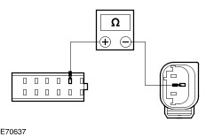
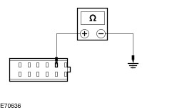
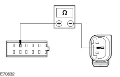
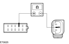
TEST the system for normal operation. | | PINPOINT TEST G : DTC B5201 : PARKING AID SPEAKER CIRCUIT OPEN CIRCUIT OR SHORT TO GROUND | | TEST CONDITIONS | DETAILS/RESULTS/ACTIONS | | G1: CHECK THE CIRCUIT CMP09 (BN/BU) FOR OPEN | | | 1 Disconnect Parking Aid Module CMP01A. | | | 2 Disconnect Parking Aid Speaker CMP09. | | | 3 Measure the resistance between the parking aid module CMP01A pin 10, circuit CMP09 (BN/BU), harness side and the parking aid speaker CMP09 pin 1, circuit CMP09 (BN/BU), harness side. | | | Is the resistance less than 1 Ohm? Yes No REPAIR the circuit. TEST the system for normal operation. | | G2: CHECK THE CIRCUIT CMP09 (BN/BU) FOR OPEN | | | 1 Measure the resistance between the parking aid module CMP01A pin 2, circuit RMP09 (BU/GN), harness side and the parking aid speaker CMP09 pin 2, circuit RMP09 (BU/GN), harness side. | | | Is the resistance less than 1 Ohm? Yes No REPAIR the circuit. TEST the system for normal operation. | | G3: CHECK THE CIRCUIT CMP09 (BN/BU) FOR SHORT TO GROUND | | | 1 Measure the resistance between the parking aid module CMP01A pin 10, circuit CMP09 (BN/BU), harness side and ground. | | | Is the resistance greater than 10,000 Ohms? Yes No REPAIR the circuit. TEST the system for normal operation. | | G4: CHECK THE CIRCUIT RMP09 (BU/GN) FOR SHORT TO GROUND | | | 1 Measure the resistance between the parking aid module CMP01A pin 2, circuit RMP09 (BU/GN), harness side and ground. | | | Is the resistance greater than 10,000 Ohms? Yes INSTALL a new parking aid module.
REFER to: Parking Aid Module (413-13 Parking Aid, Removal and Installation).
TEST the system for normal operation. No REPAIR the circuit. TEST the system for normal operation. | | PINPOINT TEST H : DTC B5212 : PARKING AID SPEAKER CIRCUIT SHORT TO POWER | | TEST CONDITIONS | DETAILS/RESULTS/ACTIONS | | H1: CHECK THE PARKING AID SPEAKER FOR CORRECT OPERATION | | | 1 Remove the parking aid speaker. | | | 2 Measure the resistance between the parking aid speaker C947 pin 1, and pin 2, component side. | | | Is the resistance 50 Ohms +/- 7.5 Ohms? Yes No INSTALL a new parking aid speaker. TEST the system for normal operation. | | H2: CHECK THE CIRCUIT CMP09 (BN/BU) FOR SHORT TO POWER | | | 1 Disconnect Parking Aid Module CMP01A. | | | 2 Disconnect Parking Aid Speaker CMP09. | | | 3 Measure the voltage between the parking aid module CMP01A pin 10, circuit CMP09 (BN/BU), harness side and ground. | | | Is the voltage less than 1 volts? Yes No REPAIR the circuit. TEST the system for normal operation. | | H3: CHECK THE CIRCUIT RMP09 (BU/GN) FOR SHORT TO POWER | | | 1 Measure the resistance between the parking aid module CMP01A pin 2, circuit RMP09 (BU/GN), harness side and ground. | | | Is the voltage less than 1 volts? Yes INSTALL a new parking aid module.
REFER to: Parking Aid Module (413-13 Parking Aid, Removal and Installation).
TEST the system for normal operation. No REPAIR the circuit. TEST the system for normal operation. | |