| Diagnosis and Testing Refer to Wiring Diagrams Section 417-01, for schematic and connector information. Special Tool(s) | | Set of adapter plugs for test probes 29-011A | Inspection and Testing NOTE:The generic electronic module (GEM) forms part of the central junction box (CJB). NOTE:If the generic electronic module (GEM) is changed, the new one must be reinitialized. For this purpose, the vehicle-specific data is read out of the module to be replaced using WDS and is transferred to the new module. REFER to: Kommunikations-Netzwerk (418-00, Diagnosis and Testing), Zentralelektrikmodul (GEM) (419-10, Diagnosis and Testing). NOTE:Before reading out the vehicle-specific data, remake all the electrical connections to the module to be removed, so that communication between the module and WDS is ensured. - Verify the customer concern.
- Visually inspect for obvious signs of electrical or mechanical damage.
Visual Inspection Chart | Electrical | - Fuse(s)
- Switch
- Electrical connector(s)
- Wiring loom
| - Resolve any obvious causes or concerns found during the visual inspection before carrying out any further tests.
- If the cause of the concern cannot be found by visual inspection, continue with the symptom chart.
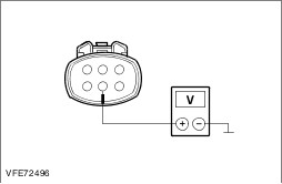
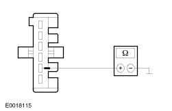
Symptom chart Symptom chart | Symptom | Possible Sources | Action | | Reversing lamps do not operate | * Fuse(s) * Circuit(s) * Reversing lamp switch * Central junction box (CJB) | * | | One reversing lamp is inoperative | * Fuse(s) * Circuit(s) * Rear lamp assembly | * | | The reversing lamps are on continuously | * Circuit(s) * Reversing lamp switch * Parking aid module * Powertrain control module (PCM) * Rear lamp assembly * Trailer socket | * | Pinpoint test NOTE:Use a digital multimeter for all electrical measurements. | PINPOINT TEST A : REVERSING LAMPS DO NOT OPERATE | | TEST CONDITIONS | DETAILS/RESULTS/ACTIONS | | A1: CHECK FUSE F33 (10 A) (EJB) | | | 1 Ignition switch in position 0. | | | 2 Disconnect fuse F33 (10 A) (EJB). | | | 3 CHECK fuse F33 (10 A) (EJB). | | | Is the fuse OK? Yes No RENEW fuse F33 (10 A) (EJB) and CHECK the operation of the system. If the fuse blows again, LOCATE and RECTIFY the short to ground using the Wiring Diagrams. CHECK the operation of the system. | | A2: CHECK THE VOLTAGE SUPPLY TO FUSE F33 (10A) (EJB) FOR OPEN CIRCUIT | | | 1 Connect fuse F33 (10 A) (EJB). | | | 2 Ignition switch in position II. | | | 3 Measure the voltage between fuse F33 (10A) (EJB) and ground. | | | Does meter display battery voltage? Yes No RENEW THE EJB. CHECK the operation of the system. | | A3: CHECK THE POWER SUPPLY OF THE REVERSING LAMP SWITCH FOR OPEN CIRCUIT | | | 1 Ignition switch in position 0. | | | 2 Disconnect Reversing lamp switch from CET47. | | | 3 Ignition switch in position II. | | | 4 Measure the voltage between reversing lamp switch, connector CET47, pin 2: - Box van, bus, combi: circuit CBB33B (WH/BN), wiring harness side and ground.
- Chassis cab vehicle: circuit CBB33B (GY/BK), wiring harness side and ground.
| | | Does the meter display battery voltage? Yes No LOCATE and RECTIFY the break in the circuits between fuse F33 (10 A) (EJB) and the reversing lamp switch using the wiring diagrams. CHECK the operation of the system. | | A4: RULE OUT THE REVERSING LAMP SWITCH AS CAUSE OF THE FAULT | | | 1 Ignition switch in position 0. | | | 2 Connect a fused (10 A) jumper lead at reversing lamp switch, connector CET47, between pin 1, circuit ZA113A (OG/GY), wiring harness side and pin 2: - Box van, bus, combi: circuit CBB33B (WH/BN), wiring harness side.
- Chassis cab vehicle: circuit CBB33B (GY/BK), wiring harness side.
| | | 3 Ignition switch in position II. | | | 4 CHECK the reversing lamps. | | | Do the reversing lamps illuminate? Yes RENEW the reversing lamp switch. CHECK the operation of the system. No | | A5: CHECK CIRCUIT BETWEEN REVERSING LAMP SWITCH AND CENTRAL JUNCTION BOX (CJB) FOR OPEN CIRCUIT | NOTE:The fused jumper lead used in the previous step is still connected at the reversing lamp switch. | | | 1 Ignition switch in position 0. | | | 2 Disconnect Central junction box (CJB) from connector CBP02B. | | | 3 Ignition switch in position II. | | | 4 Measure voltage between central junction box (CJB), connector CBP02B, pin 14, circuit ZA113C (OG/GY), wiring harness side and ground. | | | Does the meter display battery voltage? Yes No LOCATE and RECTIFY break in circuits between reversing lamp switch and central junction box (CJB) using the Wiring Diagrams. CHECK the operation of the system. | | A6: CHECK THE CENTRAL JUNCTION BOX (CJB) | NOTE:The fused jumper wire is still connected at the reversing lamp switch. | | | 1 Ignition switch in position 0. | | | 2 Connect a fused (10 A) jumper wire at the central junction box (CJB), connector CBP02B, between pin 14, circuit ZA113C (OG/GY) and pin 15, circuit CLS10A (GN/BN), wiring harness side. | | | 3 Ignition switch in position II. | | | 4 CHECK the reversing lamps. | | | Do the reversing lamps illuminate? Yes INSTALL a new CJB. CHECK the operation of the system. No - Box van, bus, combi: LOCATE and RECTIFY the break in the circuit between the central junction box (CJB) and soldered connection S2LS10 using the Wiring Diagrams. CHECK the operation of the system. | | A7: CHECK COMMON GROUND SUPPLY TO THE REAR LAMP ASSEMBLIES FOR OPEN CIRCUIT | | | 1 Ignition switch in position 0. | | | 2 Disconnect Left-hand rear lamp assembly from connector CLS04. | | | 3 Measure the resistance between the left-hand rear lamp assembly, connector CLS04, pin 1, circuit B_GD129U (BK/YE), wiring harness side and ground. | | | Is a resistance of less than 2 Ohms registered? Yes LOCATE and RECTIFY the break in the circuit between the central junction box (CJB) and soldered connection S4LS10 using the Wiring Diagrams. CHECK the operation of the system. No LOCATE and RECTIFY the break in the circuit between soldered connection S4D129G and ground connection GP29 with the aid of the Wiring Diagrams. CHECK the operation of the system. | | PINPOINT TEST B : ONE REVERSING LAMP IS INOPERATIVE | | TEST CONDITIONS | DETAILS/RESULTS/ACTIONS | | B1: DETERMINE THE FAULT CONDITION | | | 1 Ignition switch in position II. | | | 2 ENGAGE the reverse gear. | | | 3 CHECK the reversing lamps. | | | Is the left-hand reversing lamp inoperative? Yes No | | B2: CHECK THE VOLTAGE SUPPLY TO THE LEFT-HAND REAR LAMP ASSEMBLY FOR OPEN CIRCUIT | | | 1 Ignition switch in position 0. | | | 2 Disconnect Left-hand rear lamp assembly. - Box van, bus, combi: from connector CLS22
- Chassis cab vehicle: from connector CLS04
| | | 3 Ignition switch in position II. | | | 4 ENGAGE the reverse gear. | | | 5 Box van, bus, combi: Measure voltage between left-hand rear lamp assembly, connector CLS22, between pin 1: - Vehicles without tailgate: circuit CLS10F (GN/BN), wiring harness side and ground.
- Vehicles with tailgate or with tow bar socket: circuit CLS10G (GN/BN), wiring harness side and ground.
| | | 6 Chassis cab vehicle: Measure the voltage between left-hand rear lamp assembly, connector CLS04, pin 5, circuit CLS10J (GN/BN), wiring harness side and ground. | | | Does the meter display battery voltage? Yes No - Box van, bus, combi: LOCATE and RECTIFY the break in the circuit between soldered connection S2LS10 and the left-hand rear lamp assembly using the wiring diagrams. CHECK the operation of the system. - Chassis cab vehicle: LOCATE and RECTIFY the break in the circuit between soldered connection S4LS10 and the left-hand rear lamp assembly using the wiring diagrams. CHECK the operation of the system. | | B3: CHECK THE GROUND CONNECTION TO THE LEFT-HAND REAR LAMP ASSEMBLY FOR OPEN CIRCUIT | | | 1 Ignition switch in position 0. | | | 2 Box van, bus, combi: Measure resistance between left-hand rear lamp assembly, connector CLS22, between pin 5: - Vehicles without tailgate: circuit B_GD149B (BK/GY), wiring harness side and ground.
- Vehicles with tailgate or with tow bar socket: circuit A_GD149R (BK/GY), wiring harness side and ground.
| | | 3 Chassis cab vehicle: Measure the resistance between the left-hand rear lamp assembly, connector CLS04, between pin 1, circuit B_GD129U (BK/YE), wiring harness side and ground. | | | Is a resistance of less than 2 Ohms registered? Yes CHECK and if necessary RENEW the left-hand rear lamp assembly. CHECK the operation of the system. No - Chassis cab vehicle: LOCATE and RECTIFY the break in the circuit between left-hand rear lamp assembly and soldered connection S4D129G using the Wiring Diagrams. CHECK the operation of the system. - Box van, bus, combi vehicles with tailgate or with tow bar socket: LOCATE and RECTIFY the break in the circuit between left-hand rear lamp assembly and soldered connection S4D149A using the Wiring Diagrams. CHECK the operation of the system. - Box van, bus, combi, without tailgate or without tow bar socket: LOCATE and RECTIFY the break in the circuit between left-hand rear lamp assembly and soldered connection S4D149H using the Wiring Diagrams. CHECK the operation of the system. | | B4: CHECK THE VOLTAGE SUPPLY TO THE RIGHT-HAND REAR LAMP ASSEMBLY FOR OPEN CIRCUIT | | | 1 Ignition switch in position 0. | | | 2 Disconnect Right-hand rear lamp assembly from connector CLS26. | | | 3 Ignition switch in position II. | | | 4 ENGAGE the reverse gear. | | | 5 Box van, bus, combi: Measure voltage between right-hand rear lamp assembly, connector CLS26, between pin 1: - Vehicles without tailgate: circuit CLS10E (GN/BN), wiring harness side and ground.
- Vehicles with tailgate or with tow bar socket: circuit CLS10J (GN/BN), wiring harness side and ground.
| | | 6 Chassis cab vehicle: Measure the voltage between right-hand rear lamp assembly, connector CLS26, pin 5, circuit CLS10H (GN/BN), wiring harness side and ground. | | | Does the meter display battery voltage? Yes No - Box van, bus, combi: LOCATE and RECTIFY the break in the circuit between soldered connection S2LS10 and the right-hand rear lamp assembly using the wiring diagrams. CHECK the operation of the system. - Chassis cab vehicle: LOCATE and RECTIFY the break in the circuit between soldered connection S4LS10 and the right-hand rear lamp assembly using the wiring diagrams. CHECK the operation of the system. | | B5: CHECK THE GROUND CONNECTION TO THE RIGHT-HAND REAR LAMP ASSEMBLY FOR OPEN CIRCUIT | | | 1 Ignition switch in position 0. | | | 2 Box van, bus, combi: Measure resistance between right-hand rear lamp assembly, connector CLS26, between pin 5: - Vehicles without tailgate: circuit A_GD151K (BK/GN), wiring harness side and ground.
- Vehicles with tailgate or with tow bar socket: circuit A_GD151AA (BK/GN), wiring harness side and ground.
| | | 3 Chassis cab vehicle: Measure the resistance between the right-hand rear lamp assembly, connector CLS26, between pin 1, circuit B_GD129V (BK/YE), wiring harness side and ground. | | | Is a resistance of less than 2 Ohms registered? Yes CHECK and if necessary RENEW the right-hand rear lamp assembly. CHECK the operation of the system. No - Box van, bus, combi, without tailgate or without tow bar socket: LOCATE and RECTIFY the break in the circuit between right-hand rear lamp assembly and soldered connection S4D149H using the Wiring Diagrams. CHECK the operation of the system. - Box van, bus, combi vehicles with tailgate or with tow bar socket: LOCATE and RECTIFY the break in the circuit between right-hand rear lamp assembly and soldered connection S4D149A using the Wiring Diagrams. CHECK the operation of the system. - Chassis cab vehicle: LOCATE and RECTIFY the break in the circuit between right-hand rear lamp assembly and soldered connection S4D129G using the Wiring Diagrams. CHECK the operation of the system. | | PINPOINT TEST C : THE REVERSING LAMPS ARE ON CONTINUOUSLY | | TEST CONDITIONS | DETAILS/RESULTS/ACTIONS | | C1: RULE OUT THE REVERSING LAMP SWITCH AS CAUSE OF THE FAULT | | | 1 Ignition switch in position 0. | | | 2 Disconnect Reversing lamp switch from connector CET47. | | | 3 Ignition switch in position II. | | | 4 CHECK the reversing lamps. | | | Are the reversing lamps on continuously? Yes No RENEW the reversing lamp switch. CHECK the operation of the system. | | C2: NARROW DOWN THE CONDITIONS UNDER WHICH THE FAULT OCCURS | | | 1 Ignition switch in position 0. | | | 2 Disconnect Central junction box (CJB) from connector CBP02B. | | | 3 Ignition switch in position II. | | | 4 CHECK the reversing lamps. | | | Are the reversing lamps on continuously? Yes LOCATE and RECTIFY short to battery voltage in the circuits connected to the central junction box (CJB), connector CBP02B, pin 15 with the aid of the wiring diagrams. CHECK the operation of the system. - On vehicles with trailer socket: CHECK and if necessary RENEW the trailer socket. CHECK the operation of the system. No | | C3: ELIMINATE THE CENTRAL JUNCTION BOX (CJB) AS CAUSE FOR THE SHORT TO BATTERY VOLTAGE | | | 1 Measure voltage between reversing lamp switch, connector CET47, pin 1, circuit ZA113A (OG/GY), wiring harness side and ground. | | | Does the meter display battery voltage? Yes LOCATE and RECTIFY short to battery voltage in circuit between reversing lamp switch and central junction box (CJB) using the Wiring Diagrams. CHECK the operation of the system. No INSTALL a new CJB. CHECK the operation of the system. | |