
Alignment: Service and Repair (page 2 of 7)
- Make
- Hummer
- Model
- H3
- Engine
- L5-3.7L
- Year
- 2007
- Section
- Alignment › Service and Repair
bolt.
6. Manually push the rear of the vehicle down approximately 38 mm (11/2 in), gently remove hands and let the vehicle settle.
7. Repeat the above step two more times for a total of three times.
Measure both the right and left sides of the vehicle. Refer to Trim Height Specifications.
Front Caster and Camber Adjustment
Front Caster and Camber Adjustment
Tools Required
J 45938 Alignment Socket
1. The caster and camber adjustments are made by rotating the offset cam bolt and the cam in the slotted frame bracket in order to reposition the
control arm.
Important: Before adjusting the caster and camber angles, jounce the front bumper 3 times to allow the vehicle to return to normal
height.
Measure and adjust the caster and the camber with the vehicle at curb height. The front suspension Z dimension is indicated in Trim
Heights. Refer to Trim Height Specifications.
For an accurate reading, do not push or pull on the tires during the alignment process.
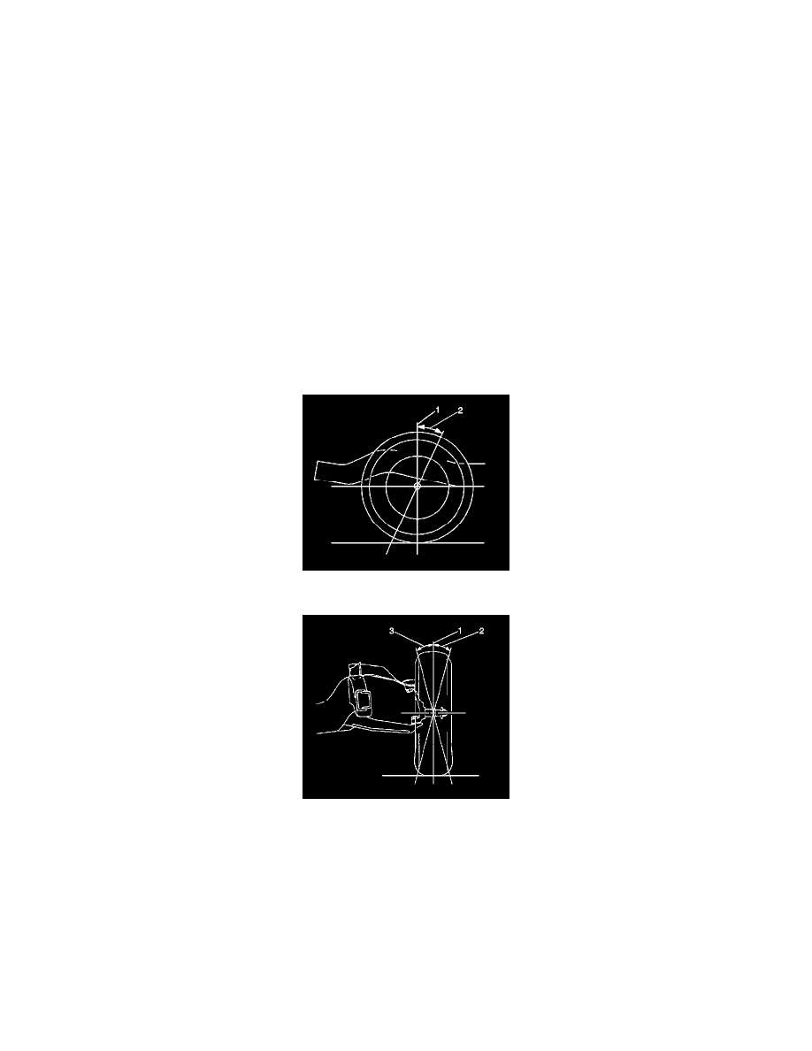
2. Determine the caster angle (2). Be sure to compensate for frame angle where required.
3. Determine the positive camber (2) or negative camber (3) angle.
Pinch or Ctrl + scroll to zoom. Double-tap to reset.
Parts & tools for this job For 2007 Hummer H3 3.7L
- TOOLTie rod end toolSearch: tie rod end puller
- TOOLBall joint separatorSearch: ball joint separator
- FLUIDPower steering fluidSearch: Hummer power steering fluid
Links open Amazon search results in a new tab. As an Amazon Associate I earn from qualifying purchases.