
Hombre S Regular Cab 4WD V6-4.3L (1999)
Electronic Brake Control Module: Service and Repair
Removal Procedure
Important: After installation, calibrate the new EBCM to the tire size that is appropriate to the vehicle. Refer to Antilock Brake Systems;
Testing and Inspection; Procedures; Description of On-Board Diagnostics; Scan Tool Diagnosis.
1. Disconnect Negative Battery Cable.
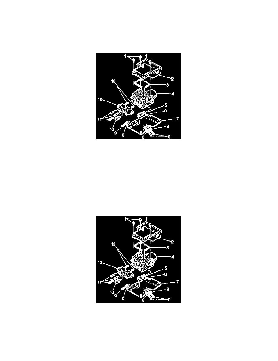
2. Remove the four T-25 Torx or screws (1) that fasten the EBCM to the BPMV.
3. Partially remove the EBCM (2) from the BPMV (4) enough to access the electrical connectors. Removal may require a light amount of force.
Important: Do not use a tool to pry the EBCM or the BPMV. Excessive force will damage the EBCM.
4. Disconnect the four electrical connectors from EBCM.
5. Fully remove the EBCM (2) from the BPMV (4).
Installation Procedure
Important: Do not reuse the old mounting screws. Always install new mounting screws with the new EBCM.
Important: Do not use RTV or any other type of sealant on the EBCM gasket or mating surfaces.
1. Connect the four electrical connectors to the EBCM.
2. Install EBCM (2) on to the BPMV (4).
3. Install the four new T-25 Torx screws (1) in the EBCM (2).
Tighten
Tighten the four T-25 Torx screws to 5 N.m (39 lb. in.) in an X-pattern.
4. Connect the negative battery cable.
5. Revise the tire calibration using the scan tool.
6. Return to Antilock Brake System; Testing and Inspection; Procedures; Diagnostic Stratagies.