
Hombre XS Space Cab L4-2.2L CPC (1997)
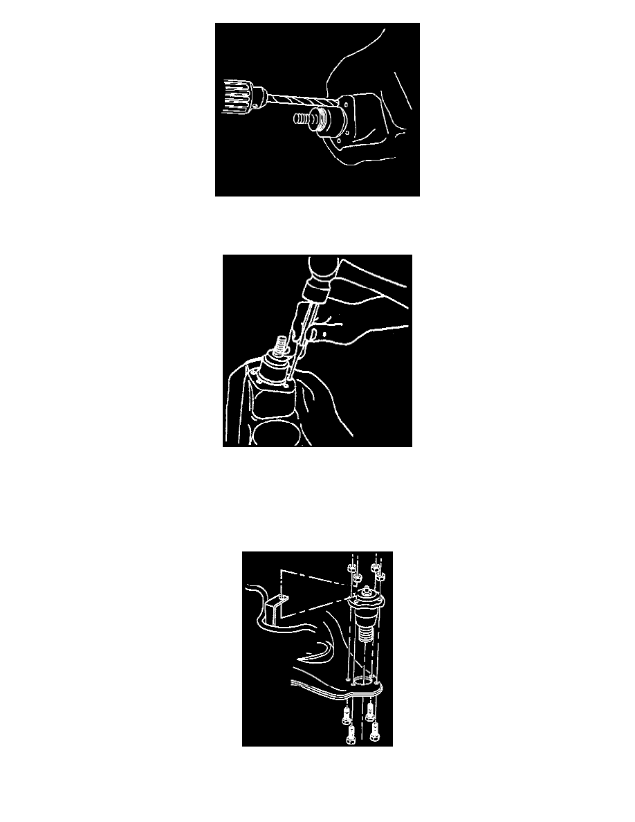
6. Remove the rivets from the upper ball joint by using a 3.175 mm (1/8 inch) drill to cut a 6.35 mm (1/4 inch) deep hole in the center of each rivet
then do the following.
^
Drill the rivet heads away using a 12.7 mm (1/2 inch) drill.
^
Punch the rivets out using a small pin punch.
7. Remove the upper ball joint.
INSTALLATION
1. Insert the new upper ball joint into the upper control arm.
2. Attach the antilock brake sensor wire bracket.
3. Position four attaching bolts and nuts and tighten them to 23 Nm (17 ft. lbs.) then take the support away from the knuckle assembly.
4. Place the upper ball joint onto the steering knuckle.
5. Install the stud nut tightening it to 83 Nm (61 ft. lbs.) making sure to align the slot in the stud nut with the hole in the stud by tightening the stud