
Hombre XS Space Cab L4-2.2L CPC (1997)
Ball Joint: Testing and Inspection
NOTE:
^
The Special Service Tool (SST) required to complete this inspection is a J 8001 dial indicator.
^
Make sure the vehicle rests on a level surface. Raise the vehicle and support it with safety stands. Support the lower control arm with a floor stand
or jack as far outboard as possible under the stabilizer bar bracket.
^
The vehicle must be stable and should not rock on the floor stands.
^
The upper control arm bumper must not contact the frame.
PROCEDURE
1. Wipe the ball joints clean and check the seals for cuts or tears, if a seal is cut or torn, the ball joint MUST be replaced.
2. Adjust the wheel bearings.
3. Check the ball joints for horizontal looseness by doing the following.
a. Position a dial indicator against the lowest outboard point on the wheel rim.
b. Rock the wheel in and out while reading the dial indicator. This will show horizontal looseness in both joints.
c. The dial indicator reading should be no more than 3.18 mm (0.125 inch). If the reading is too much, check the lower ball joints for vertical
looseness.
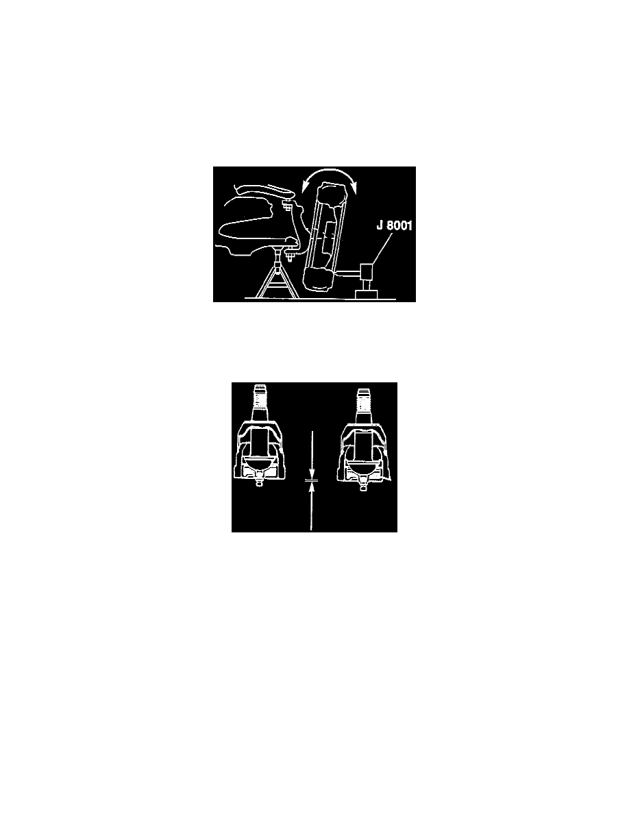
4. Check the lower ball joints for wear and vertical looseness by doing the following.
a. The lower ball joint is inspected for wear by sight. Wear is indicated by the position of the housing into which the grease fitting is
threaded. This round housing projects 1.27 mm (0.050 inch) beyond the surface of the ball joint cover on a new joint. Normal wear will
result in the surface of this housing retreating very slowly inward.
b. Observe or scrape a scale, screwdriver or fingernail across the cover. If the round housing is flush or inside the cover surface, replace the
ball joint.