
Rodeo LS 4WD V6-3.2L (1998)
-
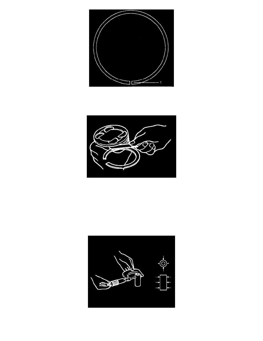
Positioning mark (1) is painted as shown in the illustration.
Marked T: No.1 Compression ring
Marked T2: No.2 Compression ring
2. Measure the clearance between the piston ring groove and the piston ring with a feeler gauge. If the piston ring groove/piston ring clearance
exceeds the specified limit, the piston must be replaced.
Compression Ring Clearance
Standard: 0.025 mm - 0.065 mm (0.0006 inch - 0.0015 inch)
Limit: 0.1 mm (0.0059 inch)
Piston Pin (9)
NOTE: Do not reuse the old piston pin.
1. Use a micrometer to measure the new piston pin outside diameter in both directions at three different positions.
2. Measure the inside diameter of the connecting rod small end. If the fitting interference between the small end and pin does not conform to the
specified value, the connecting rod must be replaced.