
Rodeo LS 4WD V6-3.2L (1998)
Standard: 0.023 mm - 0.038 mm (0.0009 inch - 0.0015 inch)
3. Insert the new pin into the piston and rotate it. If the pin rotates smoothly with no backlash, the clearance is normal. If there is backlash or
roughness, measure the clearance. If the clearance exceeds the specified limit, the piston must be replaced.
Clearance
Standard: 0.010 mm - 0.017 mm (0.0004 inch - 0.0007 inch)
Limit: 0.040 mm (0.0016 inch)
Connecting Rods (11)
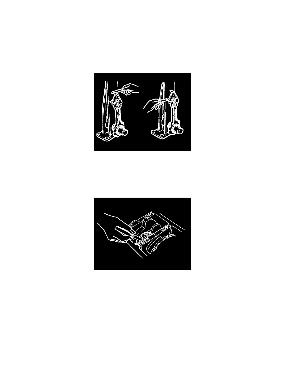
1. Check the connecting rod alignment
If either the bend or the twist exceeds the specified limit, the connecting rod must be replaced.
Bend per 100 mm (3.937 inch)
Limit: 0.15 (0.0059)
Twist per 100 mm (3.937 inch)
Limit: 0.20 (0.0078)
2. Measure the connecting rod thrust clearance. Use a feeler gauge to measure the thrust clearance at the large end of the connecting rod If the
clearance exceeds the specified limit, the connecting rod must be replaced.
Standard: 0.16 mm - 0.35 mm (0.0063 inch - 0.0138 inch)
Limit: 0.40 mm (0.0157 inch)
3. Measure the oil clearance between the connecting rod and the crankshaft.
1. Remove the connecting rod cap nuts and the rod caps (12).
Arrange the removed rod caps in the cylinder number order.
2. Clean the rod bearings and the crankshaft pins.