
Rodeo S 2WD L4-2.2L (1999)
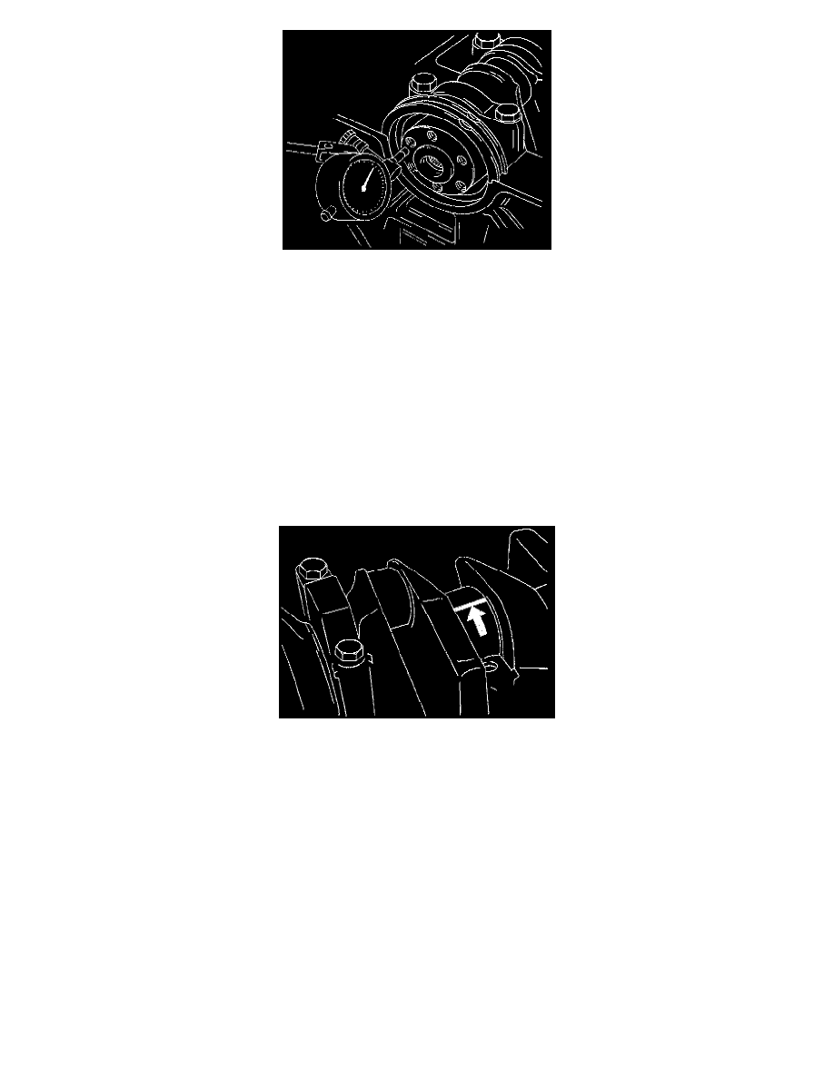
Set the dial indicator as shown in the illustration and measure the crankshaft thrust clearance. If the thrust clearance exceeds the specified limit,
replace the thrust bearings as a set.
Thrust Clearance
Standard: 0.01 mm - 0.02 mm (0.0004 inch - 0.0008 inch)
Limit: 0.21 mm (0.0118 inch)
Main Bearing Clearance
1. Remove the bearing caps and measure the oil clearance.
2. Remove the main bearing cap fixing bolts. Arrange the removed main bearing caps in the cylinder number order. Remove the main bearings.
3. Remove the crankshaft. Remove the main bearings.
4. Clean the upper and lower bearings as well as the crankshaft main journal.
5. Check the bearings for damage or excessive wear. The bearings must be replaced as a set if damage or excessive wear is discovered during
inspection.
6. Set the upper bearings and the thrust washers to their original positions. Carefully install the crankshaft.
7. Set the lower bearings to the bearing cap original position.
8. Apply plastigage to the crankshaft journal unit as shown in the illustration.
9. Install main bearing caps, and tighten each bolt to the specified torque
Main bearing caps bolts.
Torque:
1st step: 50 Nm (37 ft. lbs.)
2nd step: 45°
3rd step: 15°
Torque: 39 Nm (29 ft. lbs.)