
Alignment: Specifications (page 3 of 4)
- Make
- Jeep
- Model
- Commander 2WD
- Engine
- V6-3.7L VIN K
- Year
- 2006
- Section
- Alignment
Alignment: Service and Repair
CAMBER, CASTER AND TOE ADJUSTMENT
NOTE: SUSPENSION HEIGHT MEASUREMENT MUST BE PERFORMED BEFORE AN ALIGNMENT.
Camber and caster angle adjustments involve changing the position of the lower control arm with the slots in the frame brackets to move the lower
control arm inwards or outwards for proper adjustment. This can be achieved by using a long pry bar with a curved tip and inserting the pry bar into
the lower control arm frame brackets and prying inwards or outwards.
NOTE: Camber and caster adjustments must be made at the lower control arm. Do not use the upper control arm for Camber and Caster adjustments.
NOTE: When the lower control arm pivot bolts are loosened the lower control arm will normally go outwards automatically with the weight of the
vehicle.
CASTER
Moving the rear position of the lower control arm at the frame in or out, will change the caster angle significantly and camber angle only slightly To
maintain the camber angle while adjusting caster, move the rear of the lower control arm in or out. Then move the front of the lower control arm
slightly in the opposite direction.
CAMBER
Move both the front and rear of the lower control arm together in or out. This will change the camber angle significantly and caster angle slightly.
After adjustment is made tighten the lower control arm bolt & nuts to FRONT 169 Nm (125 ft. lbs.) and the REAR 88 Nm (65 ft. lbs.).
TOE ADJUSTMENT
The wheel toe position adjustment is the final adjustment.
1. Start the engine and turn wheels both ways before straightening the wheels. Secure the steering wheel with the front wheels in the straight-ahead
position.
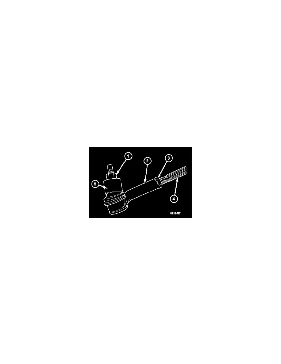
2. Loosen the tie rod jam nuts (3).
NOTE: Each front wheel should be adjusted for one-half of the total toe position specification. This will ensure the steering wheel will be centered
when the wheels are positioned straight ahead.
3. Adjust the wheel toe position by turning the inner tie rod (4) as necessary.
4. Tighten the tie rod jam nut (3) to 75 Nm (55 ft. lbs.).
5. Verify the specifications.
6. Turn off engine.
TOE ADJUSTMENT
SUSPENSION HEIGHT MEASUREMENT MUST BE PERFORMED BEFORE AN ALIGNMENT.
Pinch or Ctrl + scroll to zoom. Double-tap to reset.
Parts & tools for this job For 2006 Jeep Commander 3.7L
- TOOLTie rod end toolSearch: tie rod end puller
- TOOLBall joint separatorSearch: ball joint separator
- FLUIDPower steering fluidSearch: Jeep power steering fluid
Links open Amazon search results in a new tab. As an Amazon Associate I earn from qualifying purchases.