
Brake servo - r.r.
- Make
- Lancia
- Model
- Thesis Factory Service Manual
- Year
- 2002–2009
- Section
- Hydraulic braking system › Brake servo - r.r.
BRAKE SERVO - R.R.
Removing
- Disconnect the negative battery terminal.
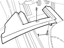
1. Undo the bolts fixing the trim under the dashboard, driver's side.
2. Remove the trim under the dashboard, driver's side.
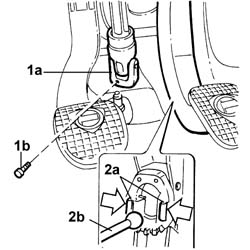
1. Release the steering column universal joint (1a) undoing the bolt (1b) fixing it to the steering box.
2. Working on the brake pedal, release the clips (2a) fastening the brake servo push rod (2b), then release it from the brake pedal.
- Position the vehicle on a lift.
See in Op. 7055B54 PROTECTION/GUARD under engine - R.R.
See in Op. 1016A10 SOUND-PROOFING COVER - R.R.
See in Op. 7040D50 ENGINE COMPARTMENT UPPER SOUND INSULATION SHIELD - R.R.
See in Op. 1016A40 Ignition COIL COVER on cylinder head - R.R.
See in Op. 7040D50 ENGINE COMPARTMENT UPPER SOUND INSULATION SHIELD - R.R.
See in Op. 1016A40 Ignition COIL COVER on cylinder head - R.R.
See in Op. 7040D50 ENGINE COMPARTMENT UPPER SOUND INSULATION SHIELD - R.R.
See in Op. 1016A40 Ignition COIL COVER on cylinder head - R.R.
See in Op. 7040D50 ENGINE COMPARTMENT UPPER SOUND INSULATION SHIELD - R.R.
See in Op. 1016A10 SOUND-PROOFING COVER - R.R.
See in Op. 7040D50 ENGINE COMPARTMENT UPPER SOUND INSULATION SHIELD - R.R.
See in Op. 1048B44 RIGID air supply PIPE from heat exchanger to intake manifold - R.R.
See in Op. 3330C40 brake fluid reservoir plug - r + r
See in Op. 3330C30 brake fluid reservoir - r + r and wash inside
See in Op. 3340A12 A.B.S. hydraulic and electronic CONTROL UNIT - R.R. - Includes bleeding air
1. Working from inside the vehicle, undo the nuts fixing the pedal assembly to the brake servo
2. Working from the engine compartment, disconnect the vacuum intake pipe from the single-acting valve connector on the brake servo.
3. Remove the brake servo/brake pump assembly from the engine compartment.
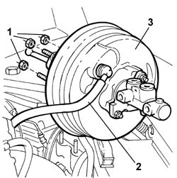
- If necessary, separate the rigid pipes connected to the ABS hydraulic and electronic control units and the brke pump from the brake servo at the bench.
When refitting the brake pump on the brake servo, NO adjustments are required.
Refitting
- If they have been removed at the bench, fit the rigid pipes connected to the ABS hydraulic and electronic control units and the brake pump.
- Position the brake servo/brake pump assembly in the housing in the engine compartment.
- Tighten the nuts fixing the brake servo to the pedal asssembly to torque.
| Value - daNm | Fastening | Component | Ø | |
|---|---|---|---|---|
| 1.4 | Nut | BRAKE SERVO | M8 |
- Connect the vacuum intake pipe on the connector for the single-acting valve on the brake servo.
See in Op. 3340A12 A.B.S. hydraulic and electronic CONTROL UNIT - R.R. - Includes bleeding air
See in Op. 3330C30 brake fluid reservoir - r + r and wash inside
See in Op. 3330C40 brake fluid reservoir plug - r + r
See in Op. 1016A10 SOUND-PROOFING COVER - R.R.
See in Op. 7040D50 ENGINE COMPARTMENT UPPER SOUND INSULATION SHIELD - R.R.
See in Op. 1016A40 Ignition COIL COVER on cylinder head - R.R.
See in Op. 7040D50 ENGINE COMPARTMENT UPPER SOUND INSULATION SHIELD - R.R.
See in Op. 1016A40 Ignition COIL COVER on cylinder head - R.R.
See in Op. 7040D50 ENGINE COMPARTMENT UPPER SOUND INSULATION SHIELD - R.R.
See in Op. 1016A40 Ignition COIL COVER on cylinder head - R.R.
See in Op. 7040D50 ENGINE COMPARTMENT UPPER SOUND INSULATION SHIELD - R.R.
See in Op. 1048B44 RIGID air supply PIPE from heat exchanger to intake manifold - R.R.
See in Op. 7040D50 ENGINE COMPARTMENT UPPER SOUND INSULATION SHIELD - R.R.
See in Op. 1016A10 SOUND-PROOFING COVER - R.R.
- Fit the brake servo push rod in the special housing on the pedal.
- Reposition the steering column universal joint securing it by tightening the fixing bolt to the recommended torque.
| Value - daNm | Fastening | Component | Ø | |
|---|---|---|---|---|
| 2 | Bolt | STEERING SHAFT MOUNTING | M8 |
- Fit the trim under the dashboard, driver's side, in the special housing and secure it using the bolts.
- [0010T64]
- [0010T65]
- Connect the negative battery terminal.
See in Op. 7055B54 PROTECTION/GUARD under engine - R.R.
- Remove the vehicle from the lift.
Parts & tools for this job For 2002 Lancia Thesis
- PARTBrake padsSearch: Lancia Thesis 2002 brake pads
- TOOLBrake bleeder kitSearch: one man brake bleeder kit
- FLUIDBrake fluidSearch: brake fluid
Links open Amazon search results in a new tab. As an Amazon Associate I earn from qualifying purchases.