
Right CYLINDER HEAD - Overhaul - Dismantling
- Make
- Lancia
- Model
- Thesis Factory Service Manual
- Year
- 2002–2009
- Section
- Cylinder head – s › Right CYLINDER HEAD - Overhaul - Dismantling
Right CYLINDER HEAD - Overhaul - Dismantling
Removing
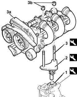
1. Place the tool A in the vice.
| Description | Code | Function | |
|---|---|---|---|
| 1 | Support | 1.860.783.000 |
2. Fit the tool (2a) A complete with the tool (2b) A.
| Description | Code | Function | |
|---|---|---|---|
| 2a | Support | 1.860.784.000 |
| Description | Code | Function | |
|---|---|---|---|
| 2b | Bearings | 1.860.952.000 |
3. Position the cylinder head (3a) on the support tools and fasten it using the nuts (3b).
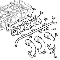
1. Undo the bolts (1a) and remove the intake manifolds (1b).
2. Undo the bolts (2a) and remove the fuel distribution manifold (2b) with injectors (2c).
3. Remove the air intake manifold (3a) complete with gasket (3b).
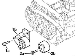
1. Undo the bolts (1a) and remove the timing drive belt automatic belt tensioner (1b).
2. Undo the bolt (2a) and remove the timing drive belt fixed belt tensioner (2b).
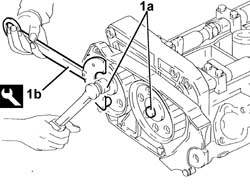
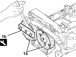
1. Loosen the bolts (1a) for the camshaft drive pullies using the tools (1b) A for counter-torque.
| Description | Code | Function | |
|---|---|---|---|
| 1b | Support for counter-torque | 1.860.831.000 | Support |
1. Remove the camshaft drive pullies (1a) using the tool (1b) A.
| Description | Code | Function | |
|---|---|---|---|
| 1b | Extractor | 1.860.954.000 |
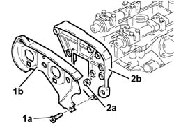
1. Undo the bolts (1a) and remove the timing belt guard (1b).
2. Undo the nuts (2a) and remove the reaction rod support (2b).
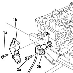
1. Undo the bolt (1a) and remove the coolant outlet connector (1b) from the right cylinder head.
2. Undo the bolt (2a) and remove the cam angle sensor (2b) complete with O-Ring (2c).
- Check that the camshaft endfloat M is within the recommended values using a dial gauge on a mangetic base.
| Subject | Value | |
|---|---|---|
| Camshafts | ||
| End float | 0.060 - 0.201 |
- If the camshaft endfloat does not correspond to the recommended figures, replace the worn components when reassembling.
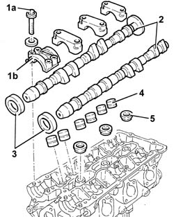
1. Undo the bolts (1a) and remove the camshaft caps (1b).
2. Remove the camshafts.
3. Remove the camshaft front oil seals.
4. Remove the hydraulic tappets.
5. Remove the spark plug seat seals.
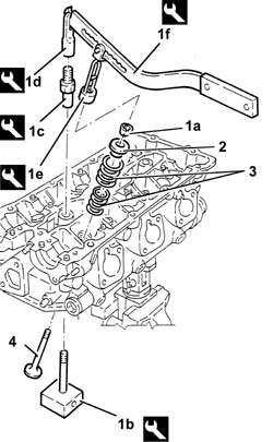
1. 1. Remove the cotters (1a) using the tools (1b), (1c), (1d), (1e) and (1f) A.
| Description | Code | Function | |
|---|---|---|---|
| 1b | Valve support | 1.860.786.000 |
| Description | Code | Function | |
|---|---|---|---|
| 1c | Special nut | 1.860.787.000 |
| Description | Code | Function | |
|---|---|---|---|
| 1d | Support | 1.860.788.000 | Removing/refitting valves |
| Description | Code | Function | |
|---|---|---|---|
| 1e | Chamber | 1.860.840.000 |
| Description | Code | Function | |
|---|---|---|---|
| 1f | Lever | 1.860.790.000 |
2. Remove the valve upper shim.
3. Remove the valve springs.
- Remove the tools used for dismantling the valves.
4. Remove the valve.
- Carry out the same operations for removing the remaining valves.
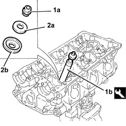
1. Remove the valve guide oil seal (1a) using the tool (1b) A.
| Description | Code | Function | |
|---|---|---|---|
| 1b | Extractor | 1.860.835.000 |
2. Remove the spring lower seal (2a) and the valve lower shim (2b).
- Remove the cylinder head from the support tools and place it on a special workbench.
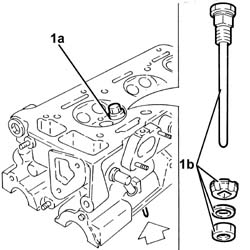
1. Thread the special extraction tool (b) into the valve seat (1a).
- Turn the cylinder head upsidedown on the workbench.
- Remove the valve seat using the extraction tool.
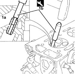
1. Remove the valve guides (1a) using the tool (1b) A.
| Description | Code | Function | |
|---|---|---|---|
| 1b | Extractor | 1.860.395.000 |
Refitting
- Clean any residues of the old gasket from the lower cylinder head plane.
1. Check that the planarity of the lower cylinder head plane M corresponds to the recommended values.
| Subject | Value | |
|---|---|---|
| 1 | Cylinder head | |
| Lower plane planarity | 0.05 |
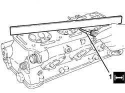
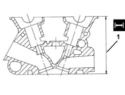
1. If the planarity of the lower cylinder head plane does not correspond to the recommended figures, regrind it without exceeding the minimum permitted height M.
| Subject | Value | |
|---|---|---|
| 1 | Cylinder head | |
| Minimum permitted height after refacing | 134.85 - 135.15 |
- Check that the valves do not show signs of grooves or seizing.
- Check that the diameter of the valve stems M corresponds to the recommended figures; if not, replace the worn valves.
| Subject | Value | |
|---|---|---|
| Valves | ||
| Stem diameter | 6.965 - 6.980 |
- Check that the outer diameter of the hydraulic tappets M corresponds to the recommended figures; if not, replace the worn hydraulic tappets.
| Subject | Value | |
|---|---|---|
| Hydraulic tappets | ||
| Outer diameter | 32.959 - 32.975 |
- Check that the diameter of the hydraulic tappet housings M corresponds to the recommended figures; if not, replace the cylinder head.
| Subject | Value | |
|---|---|---|
| Cylinder head | ||
| Hydraulic tappet housing diameter | 33.000 - 33.025 |
- Check that the length of the valve springs M released corresponds to the recommended figures.
| Subject | Value | ||
|---|---|---|---|
| Valve springs | |||
| Free length | |||
| Outer | 45 | ||
| Inner | 42 |
- Using a torque wrench, check that the spring M specifications correspond to the recommended figures; if not, replace the springs.
| Subject | Value | |
|---|---|---|
| Valve springs | ||
| Length with load | 22.4 - 23.6 | |
| Outer | 32.5 |
| Subject | Value | |
|---|---|---|
| Valve springs | ||
| Length with load | 45.9 - 43.9 | |
| Outer | 23 |
| Subject | Value | |
|---|---|---|
| Valve springs | ||
| Length with load | 12.6 - 13.4 | |
| Inner | 30.5 |
| Subject | Value | |
|---|---|---|
| Valve springs | ||
| Length with load | 23.5 - 26.5 | |
| Inner | 21 |
- Check that the diameter of the camshaft bearings M corresponds to the recommended figures; if not, replace the worn components.
| Subject | Value | |
|---|---|---|
| Camshafts | ||
| Journal diameter | 26.959 - 26.980 |
- Check that the nominal camshaft cam lift M corresponds to the recommended figures; if not, replace the worn components.
| Subject | Value | |
|---|---|---|
| Camshafts | ||
| Nominal cam lift | 9.30 |
1. Fit the camshaft caps on the right cylinder head following the order illustrated in the diagram.
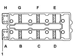
1. Tighten the camshaft cap bolts to torque C.
| Value - daNm | Fastening | Component | Ø | |
|---|---|---|---|---|
| 1.8 - 2.5 | Bolt | CAMSHAFT CAPS | M8 |
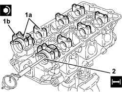
2. Check that the diameter of the camshaft supports M corresponds to the recommended figures; if not, replace the cylinder head.
| Subject | Value | |
|---|---|---|
| 2 | Cylinder head | |
| Diameter of camshaft supports | 27.010 - 27.036 |
- Check that the outer diameter of the valve guides M to be fitted corresponds to the recommended figures.
| Subject | Value | ||
|---|---|---|---|
| Valve guides | |||
| Outer diameter | |||
| Inlet | 12.040 - 12.051 | ||
| Exhaust | 12.050 - 12.068 |
| Subject | Value | |
|---|---|---|
| Cylinder head valve guides | mm | |
| Valve guide oversize | 0.20 | |
| Spares (*) | 12.053 - 12.064 |
| Subject | Value | |
|---|---|---|
| Cylinder head valve guides | mm | |
| Valve guide oversize | 0.20 | |
| Spares (**) | 12.064 - 12.082 |
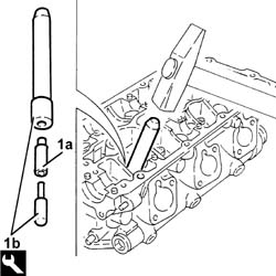
1. Fit the valve guides (1a) using the tool (1b) A.
| Description | Code | Function | |
|---|---|---|---|
| Fitting tool | 1.860.947.000 |
- Ream the valve guide inner diameter M to the recommended figure.
| Description | Code | Function | |
|---|---|---|---|
| Reamer | 1.890.313.000 | Ream |
| Subject | Value | |
|---|---|---|
| Valve guides | ||
| Inner diameter (reaming) | 7.000 - 7.015 |
- Check that the outer diameter of the valve seats M to be fitted corresponds to the recommended figures.
| Subject | Value | ||
|---|---|---|---|
| Valve seats | |||
| Outer diameter | |||
| Inlet | 35.500 - 35.900 | ||
| Exhaust | 31.000 - 31.200 |
| Subject | Value | |
|---|---|---|
| Cylinder head valve seats (all) | mm | |
| Oversize | 0.3 |
| Subject | Value | |
|---|---|---|
| Cylinder head valve seats (all) | mm | |
| Oversize | 0.3 |
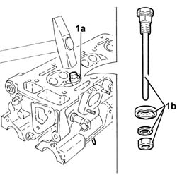
1. Heat the cylinder head to 100-120°C, then fit the valve seats (1a) using a suitable tool (1b).
| Description | Code | Function | |
|---|---|---|---|
| 1b | Fitting tool | 1.860.395.000 | Fit |
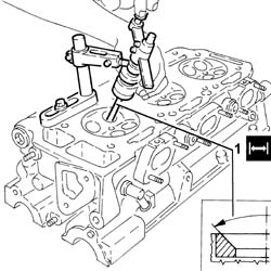
1. Regrind the valve seats to the recommended size M.
| Subject | Value | |
|---|---|---|
| 1 | Valve seats | |
| Contact band taper with valve | 90° ± 20' |
- Grind the valve seats using a suitable tool.
- Fit the cylinder head on the support tools and fasten it using the nuts.
- Fit the lower valve shim and the lower valve seal.
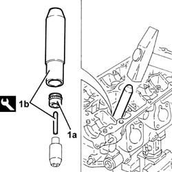
1. Fit the valve guide oil seal (1a) using the tool (1b) A.
| Description | Code | Function | |
|---|---|---|---|
| 1b | Fitting tool | 1.860.454.000 |
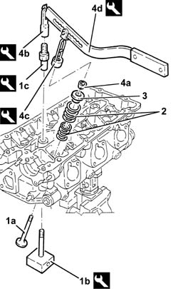
1. Fit the valves (1a) for the cylinder in question and support them using the tools (1b) and (1c) A.
| Description | Code | Function | |
|---|---|---|---|
| 1b | Valve support | 1.860.786.000 |
| Description | Code | Function | |
|---|---|---|---|
| 1c | Special nut | 1.860.787.000 |
2. Fit the valve springs.
3. Fit the upper valve shims.
4. Fit the cotters (4a) using the tools (4b), (4c), and (4d) A.
| Description | Code | Function | |
|---|---|---|---|
| 4b | Support | 1.860.788.000 | Removing/refitting valves |
| Description | Code | Function | |
|---|---|---|---|
| 4c | Chamber | 1.860.840.000 |
| Description | Code | Function | |
|---|---|---|---|
| 4d | Lever | 1.860.790.000 |
- Carry out the same operations to refit the remaining valves.
- Remove the tools used for fitting the valves.
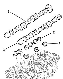
1. Fit the spark plug seat seals.
2. Fit the hydraulic tappets.
3. Fit the camshafts.
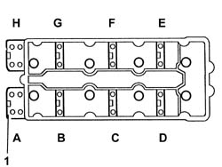
1. Fit the camshaft caps on the right cylinder head following the order illustrated in the diagram.
- Tighten the camshaft cap bolts to torque C.
| Value - daNm | Fastening | Component | Ø | |
|---|---|---|---|---|
| 1.8 - 2.5 | Bolt | CAMSHAFT CAPS | M8 |
1. Fit the camshaft front oil seals (1a) using the tool (1b) A.
| Description | Code | Function | |
|---|---|---|---|
| 1b | Fitting tool | 1.860.948.000 | Camshaft front oil seal |
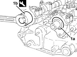
- Fit the cam angle sensor complete with O-Ring and fasten it using the bolt.
| Value - daNm | Fastening | Component | Ø | |
|---|---|---|---|---|
| 0.7 - 1.0 | Bolt | CAM ANGLE SENSOR |
- Fit the right cylinder head coolant outlet connector and fasten it using the bolt.
- Fit the reaction rod support and secure it using the nuts.
| Value - daNm | Fastening | Component | Ø | |
|---|---|---|---|---|
| 2.3 - 3.3 | Nuts | POWER UNIT REACTION ROD |
- Fit the timing belt guard and secure it using the bolts.
| Value - daNm | Fastening | Component | Ø | |
|---|---|---|---|---|
| 0.8 - 1.2 | Bolts | TIMING BELT PROTECTIVE COVER(S) |
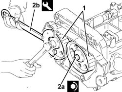
1. Fit the camshaft drive pullies.
2. Tighten the camshaft drive pulley bolts (2a) using the tools (2b) A to torque C.
| Description | Code | Function | |
|---|---|---|---|
| 2b | Support for counter-torque | 1.860.831.000 | Support |
| Value - daNm | Fastening | Component | Ø | |
|---|---|---|---|---|
| 2a | 7.3 - 10.6 | CAMSHAFT DRIVE PULLIES | M10 |
- Fit the timing drive belt fixed belt tensioner and fasten it using the bolt.
- Fit the timing drive belt automatic belt tensioner and secure it without tightening the bolts.
- Fit the intake manifold complete with gasket.
- Fit the fuel distribution manifold complete with injectors and secure it using the fixing bolts.
- Fit the intake manifolds and secure them using the bolts.
- Remove the cylinder head from the support tools.
- Remove the cylinder head support tools from the vice and put them down.
Removing
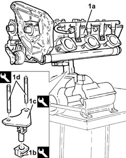
1. Position the cylinder head (1a) in the vice using the tools (1b), (1c) and (1d).
| Description | Code | Function | |
|---|---|---|---|
| 1b | Adjustable mount | 1.820.012.000 | Supporting cylinder head in vice |
| Description | Code | Function | |
|---|---|---|---|
| 1d | Studs | 1.860.952.000 | Supporting cylinder head in vice |
| Description | Code | Function | |
|---|---|---|---|
| 1c | Fork | 1.820.050.000 | Supporting cylinder head in vice |
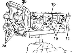
1. Undo the bolts (1a) and remove the fuel manifold pipe (1b) with injectors (1c).
2. Undo the nuts (2a) and remove the reaction rod support (2b).
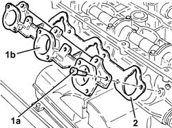
1. Undo the bolts (1a) and remove the intake manifold (1b).
2. Remove the seal.
1. Undo the bolts (1a) and remove the mobile timing belt tensioner (1b).
2. Undo the nuts (2a) and remove the bracket (2b).
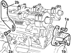
- Check that the camshaft endfloat corresponds to the recommended values using a dial gauge on a magnetic base.
| Subject | Value | |
|---|---|---|
| Cyliner head inlet and exhaust shafts | mm | |
| Camshaft end float | 0.060 ÷ 0.201 |
- If the camshaft endfloat does not correspond to the recommended figures, replace the worn components when reassembling.
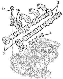
1. Undo the bolts (1a) and remove the camshaft caps (1b).
2. Remove the camshafts.
3. Remove the camshaft front oil seals.
4. Remove the hydraulic tappets.
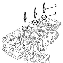
1. Remove the spark plug seat seals.
2. Remove the spark plugs.
1. Remove the cylinder half-cones (1a) using the tools (1b), (1c), (1d), (1e) and (1f).
| Description | Code | Function | |
|---|---|---|---|
| 1b | Valve support | 1.820.011.000 | Removing/refitting valves |
| Description | Code | Function | |
|---|---|---|---|
| 1f | Lever | 1.821.058.000 | Removing/refitting valves |
| Description | Code | Function | |
|---|---|---|---|
| 1e | Chamber | 1.821.205.000 | Removing/refitting valves |
| Description | Code | Function | |
|---|---|---|---|
| 1d | Support | 1.821.124.000 | Removing/refitting valves |
| Description | Code | Function | |
|---|---|---|---|
| 1c | Connector | 1.820.049.000 | Removing/refitting valves |
2. Fit the upper valve shims.
3. Remove the valve springs.
- Remove the tools used for dismantling the valves.
4. Remove the valves.
- Carry out the same operations for removing the remaining valves.
1. Remove the valve guide oil seals (1a) using the tool (1b).
| Description | Code | Function | |
|---|---|---|---|
| 1b | Extractor | 1.821.208.000 | Removing valve guide oil seals |
2. Remove the spring lower sealing rings (2a) and the valve lower shims (2b).
- Remove the cylinder head from the support tools and place it on a special workbench.
1. Remove the valve guides (1a) using the tool (1b).
| Description | Code | Function | |
|---|---|---|---|
| 1b | Extractor | 1.821.176.000 | Extracting valve guides |

Refitting
- Clean any residues of the old gasket from the lower cylinder head plane.
1. Check that the planarity of the lower cylinder head surface corresponds to the recommended values.
If grinding is necessary, adjust the flatness of both cylinder heads.
| Subject | Value | |
|---|---|---|
| 1 | Engine cylinder heads | mm |
| Cylinder head lower surface flatness | < 0.1 |

1. If the planarity of the lower cylinder head plane does not correspond to the recommended figures, regrind it without exceeding the minimum permitted height.
The minimum permitted cylinder head height must never be exceeded, otherwise the cylinder head must be replaced.
| Subject | Value | |
|---|---|---|
| 1 | Engine cylinder heads | mm |
| Minimum permitted cylinder head height | 134.85 ÷ 135.15 |

- Remove valve deposits, checking the rod for scoring or signs of binding.
- Check that the diameter of the valve stems corresponds to the recommended figures; if not, replace the worn valves.
| Subject | Value | |
|---|---|---|
| Cylinder head valves (all) | mm | |
| Valve stem diameter | 6.965 ÷ 6.980 |
- Check that the outer diameter of the hydraulic tappets corresponds to the recommended figures; if not, replace the worn hydraulic tappets.
| Subject | Value | |
|---|---|---|
| Hydraulic tappet casings | mm | |
| External hydraulic tappet diameter | 32.959 ÷ 32.97 |
- Check that the diameter of the main journal seats is within specified limits.
| Subject | Value | |
|---|---|---|
| Engine cylinder heads | mm | |
| Hydraulic tappet housing diameter | 33.000 ÷ 33.025 |
- Check that the length of the valve springs released is within the recommended values.
| Subject | Value | ||
|---|---|---|---|
| Cylinder head valve springs (all) | mm | ||
| Valve spring free length | |||
| Outer | 45.0 | ||
| Inner | 42.0 |
- Using a torque wrench, check that the valve spring specifications correspond to the recommended figures; if not, replace the worn components.
| Subject | Value | |
|---|---|---|
| Cylinder head valve springs (all) | mm | |
| External valve spring height | 32.5 | |
| Test load | 21.9 ÷ 23.1 |
| Subject | Value | |
|---|---|---|
| Cylinder head valve springs (all) | mm | |
| External valve spring height | 23,0 | |
| Test load | 43.1 ÷ 45.0 |
| Subject | Value | |
|---|---|---|
| Cylinder head valve springs (all) | mm | |
| Internal valve spring height | 30,5 | |
| Test load | 12.4 ÷ 13.1 |
| Subject | Value | |
|---|---|---|
| Cylinder head valve springs (all) | mm | |
| Internal valve spring height | 21,0 | |
| Test load, | 24.0 ÷ 26.0 |
- Check that the diameter of the camshaft journals corresponds to the recommended figures; if not, replace the worn camshafts.
The camshaft journal surfaces must not show signs of wear, scoring or binding, otherwise replace the shafts.
| Subject | Value | |
|---|---|---|
| Cyliner head inlet and exhaust shafts | mm | |
| Camshaft journal diameter | 26.959 ÷ 26.980 |
- Check that the nominal camshaft cam lift corresponds to the recommended figures; if not, replace the worn camshaft.
The camshaft cam surfaces must not show signs of wear, scoring or binding, otherwise replace the shafts.
| Subject | Value | |
|---|---|---|
| Cyliner head inlet and exhaust shafts | mm | |
| Nominal camshaft cam lift | 9.30 |
- Refit the camshaft caps on the right cylinder head following the order illustrated in the diagram.

1. Tighten the camshaft cap bolts to the recommended torque.
| Value - daNm | Fastening | Component | Ø | |
|---|---|---|---|---|
| 1 | (Cylinder head side) 1.8 -2.0 | Bolt | CAMSHAFT CAPS | M8 |
2. Check that the diameter of the camshaft mounts is as specified.
| Subject | Value | |
|---|---|---|
| Engine cylinder heads | mm | |
| Diameter of camshaft mounts | 27.010 ÷ 27.036 |

- Check that the outer diameter of the valve guides is as specified.
| Subject | Value | ||
|---|---|---|---|
| Cylinder head valve guides | mm | ||
| Valve guide outer diameter | |||
| Inlet | 12.040 ÷ 12.051 |
| Subject | Value | ||
|---|---|---|---|
| Cylinder head valve guides | mm | ||
| Valve guide outer diameter oversize | |||
| Inlet | 0.20 |
Parts supplies intake valve guides with outer diameter of 12.053 ÷ 12.064 mm
| Subject | Value | ||
|---|---|---|---|
| Cylinder head valve guides | mm | ||
| Valve guide outer diameter | |||
| Exhaust | 12.050 ÷ 12.068 |
| Subject | Value | ||
|---|---|---|---|
| Cylinder head valve guides | mm | ||
| Valve guide outer diameter oversize | |||
| Exhaust | 0.20 |
Parts supplies exhaust valve guides with outer diameter of 12.064 ÷ 12.082 mm
- Check that the valve guide seat diamters is within specified values. If not, ream the seats according to the valve guide oversize.
| Subject | Value | |
|---|---|---|
| Engine cylinder heads | mm | |
| Valve guide seat diameter | 12.000 ÷ 12.018 |
1. Refit the valve guides (1a) in their seats using installing tool (1b).
The use of the above tool ensures correct valve guide protrusion.
| Description | Code | Function | |
|---|---|---|---|
| 1b | Fitting tool | 1.821.207.000 | Fitting valve guides |

1. Ream the new valve guides using an appropriate tool to calibrate the holes to the specified diameter.
| Subject | Value | |
|---|---|---|
| 1 | Cylinder head valve guides | mm |
| Inner valve guide diameter (reaming) | 7.000 ÷ 7.015 |

1. Regrind the valve seats to the recommended size.
| Subject | Value | |
|---|---|---|
| 1 | Cylinder head valve seats (all) | |
| Contact band angle with valves | 90° ± 20' |
- Grind the valve seats using a suitable tool.
Use SIPAL Arexons abrasive or a simlar product to grind the valve seats.

- Position the cylinder head in a vice using the tools.
| Description | Code | Function | |
|---|---|---|---|
| Adjustable mount | 1.820.012.000 | Supporting cylinder head in vice |
| Description | Code | Function | |
|---|---|---|---|
| Fork | 1.820.050.000 | Supporting cylinder head in vice |
| Description | Code | Function | |
|---|---|---|---|
| Studs | 1.860.952.000 | Supporting cylinder head in vice |
- Refit the lower valve shims and the lower spring contact rings in their seats.
1. Remove the valve guide oil seals (1a) using the tool (1b).
| Description | Code | Function | |
|---|---|---|---|
| 1b | Fitting tool | 1.821.206.000 | Fitting valve guide oil seals |

1. Fit the valves (1a) for the cylinder in question and support them using the tools (1b) and (1c).
| Description | Code | Function | |
|---|---|---|---|
| 1b | Valve support | 1.820.011.000 | Removing/refitting valves |
| Description | Code | Function | |
|---|---|---|---|
| 1c | Connector | 1.820.049.000 | Removing/refitting valves |
2. Place the valve springs in their housings.
3. Refit the upper valve shims in their housings.
4. Place the cylinder valve half-cones (4a) in their housings using the tools (4b), (4c) and (4d).
| Description | Code | Function | |
|---|---|---|---|
| 4b | Support | 1.821.124.000 | Removing/refitting valves |
| Description | Code | Function | |
|---|---|---|---|
| 4c | Chamber | 1.821.205.000 | Removing/refitting valves |
| Description | Code | Function | |
|---|---|---|---|
| 4d | Lever | 1.821.058.000 | Removing/refitting valves |

- Remove the tools used for fitting the valves.
- Carry out the same operations to refit the remaining valves.
1. Fit the spark plugs and tighten them to the recommended torque.
| Value - daNm | Fastening | Component | Ø | |
|---|---|---|---|---|
| 1 | (Cylinder head side) 2.4 - 3.0 | SPARK PLUGS | M14 |

1. Test the valve seal using tools (1a) and (1b).
| Description | Code | Function | |
|---|---|---|---|
| 1a | Lever | 1.860.490.000 | Valve leakage test |
| Description | Code | Function | |
|---|---|---|---|
| 1b | Pressurising device | 1.895.868.000 | Valve leakage test |

1. Refit the spark plug socket seals.
2. Place the hydraulic tappets in their housings.
3. Place the camshafts in their housings.

- Refit the camshaft caps on the right cylinder head following the order illustrated in the diagram.

- Tighten the bolts fixing the camshaft caps to the recommended torque.
| Value - daNm | Fastening | Component | Ø | |
|---|---|---|---|---|
| (Cylinder head side) 1.8 -2.0 | Bolt | CAMSHAFT CAPS | M8 |
1. Remove the camshaft oil seals (1a) using the tool (1b).
| Description | Code | Function | |
|---|---|---|---|
| 1b | Fitting tool | 1.860.948.000 | Fitting camshaft front oil seals |

- Refit the bracket and secure with the bolt.
- Reposition the moving timing system tensioner in its housing and secure it without tightening the nut.
1. Refit the intake manifold (1a) complete with gasket (1b) back in its housing and secure it tightening the bolts (1c) to the recommended torque.
| Value - daNm | Fastening | Component | Ø | |
|---|---|---|---|---|
| 1c | (Cylinder head side) 1.9 - 2.3 | Bolt | INLET MANIFOLD | M8 |

1. Refit the reaction rod bracket (1a) in its seat and secure it by tightening the nuts (1b) to the recommended torque.
| Value - daNm | Fastening | Component | Ø | |
|---|---|---|---|---|
| 1b | (Cylinder head side) 4.5 - 5.5 | Nut | REACTION LINK BRACKET ON ENGINE | M10 |

- Place the fuel manifold pipe complete with injectors in its housing and secure it using the bolts.
- Remove the cylinder head from the support tools.
- Operation not available
Parts & tools for this job For 2002 Lancia Thesis
- PARTEngine gasket setSearch: Lancia Thesis 2002 engine gasket set
- TOOLTorque wrenchSearch: 3/8 inch torque wrench
- TOOLFeeler gauge setSearch: feeler gauge set
Links open Amazon search results in a new tab. As an Amazon Associate I earn from qualifying purchases.