
RIGID REAR power unit MOUNTING - R.R.
- Make
- Lancia
- Model
- Thesis Factory Service Manual
- Year
- 2002–2009
- Section
- Power unit supports › RIGID REAR power unit MOUNTING - R.R.
RIGID REAR power unit MOUNTING - R.R.
Removing
- Position the vehicle on a lift.
- Open the boot and disconnect the negative battery terminal.
See in Op. 7055B54 PROTECTION/GUARD under engine - R.R.
See in Op. 4450B04 Right FRONT WHEEL (one) - R.R.
See in Op. 7055B42 FRONT WHEEL ARCH LINER (one), left or right - R.R.
See in Op. 7055B64 Engine compartment DUST SEAL in front wheel arch (one), left or right - R.R.
See in Op. 2710A31 INTERMEDIATE DRIVE SHAFT - R.R.
- Lower the vehicle.
See in Op. 1016A10 SOUND-PROOFING COVER - R.R.
See in Op. 7040D50 ENGINE COMPARTMENT UPPER SOUND INSULATION SHIELD - R.R.
See in Op. 1048B44 RIGID air supply PIPE from heat exchanger to intake manifold - R.R.
See in Op. 1048A56 UPPER RESONATOR - R.R.
See in Op. 1092G10 Engine components single drive BELT - R.R.
See in Op. 1092A10 Crankshaft PULLEY - R.R.
See in Op. 1092G15 Engine components single belt MOVING TENSIONER - R.R. with belt removed
1. Undo the bolts fixing the alternator.
- Disconnect the alternator electrical wiring.
2. Remove the alternator.
| Description | Connector | |
|---|---|---|
| Alternator | A010A |
| Description | Connector | |
|---|---|---|
| Alternator | A010B |
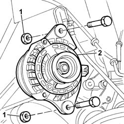
- Lower the lift.
1. Remove the alternator rear mounting bracket.
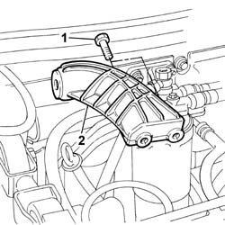
- Position the hydraulic engine support under the oil sump in order to work safely.
1. Disconnect the electrical connection for the insufficient engine oil pressure sensor.
| Description | Connector | |
|---|---|---|
| 1 | Insufficient engine oil pressure sensor | K030 |
2. Undo the nut fixing the support to the flexible mounting.
3. Undo the bolt fixing the support to the oil sump.
- Keep the spacers which are between the bolt and the sump.
4. Undo the bolts fixing the support to the cylinder block/crankcase.
5. Remove the intermediate driveshaft support which supports the engine.
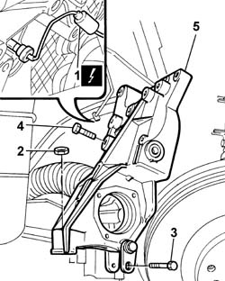
Refitting
- Position the engine support which also supports the intermediate driveshaft in the special housing.
- Tighten the bolts fixing the support to the engine support to the cylinder block/crankcase to torque.
| Value - daNm | Fastening | Component | Ø | |
|---|---|---|---|---|
| 5 | Bolt | RIGID REAR SUPPORT POWER UNIT | M10 X 1.25 |
- Tighten the bolt fixing the support to the oil sump to torque.
| Value - daNm | Fastening | Component | Ø | |
|---|---|---|---|---|
| 2.5 | Bolt | RIGID REAR SUPPORT POWER UNIT | M8 |
- Tighten the nut fixing the engine support to the flexible mounting on the chassis to torque.
| Value - daNm | Fastening | Component | Ø | |
|---|---|---|---|---|
| 4,5 | Nut | POWER UNIT REAR RIGID MOUNT | M10 X 1.25 |
- Connect the electrical connection for the insufficient engine oil pressure sensor.
| Description | Connector | |
|---|---|---|
| Insufficient engine oil pressure sensor | K030 |
- Fit the alternator mounting bracket tightening the bolts fixing it to the cylinder block/crankcase to torque.
| Value - daNm | Fastening | Component | Ø | |
|---|---|---|---|---|
| 5 | Bolt | FRONT ALTERNATOR SUPPORT | M10 |
- Fit the alternator assembly and tighten the bolts fixing it to the mounting.
| Value - daNm | Fastening | Component | Ø | |
|---|---|---|---|---|
| 5 | Nut | ALTERNATOR ASSEMBLY | M10 X 1.25 |
| Value - daNm | Fastening | Component | Ø | |
|---|---|---|---|---|
| 7 | Nut | ALTERNATOR ASSEMBLY | M12 X 1.25 |
- Connect the alternator electrical wiring.
| Description | Connector | |
|---|---|---|
| Alternator | A010A |
| Description | Connector | |
|---|---|---|
| Alternator | A010B |
See in Op. 1092G15 Engine components single belt MOVING TENSIONER - R.R. with belt removed
See in Op. 1092A10 Crankshaft PULLEY - R.R.
See in Op. 1092G10 Engine components single drive BELT - R.R.
See in Op. 1048A56 UPPER RESONATOR - R.R.
See in Op. 1048B44 RIGID air supply PIPE from heat exchanger to intake manifold - R.R.
See in Op. 7040D50 ENGINE COMPARTMENT UPPER SOUND INSULATION SHIELD - R.R.
See in Op. 1016A10 SOUND-PROOFING COVER - R.R.
See in Op. 2710A31 INTERMEDIATE DRIVE SHAFT - R.R.
See in Op. 7055B64 Engine compartment DUST SEAL in front wheel arch (one), left or right - R.R.
See in Op. 7055B42 FRONT WHEEL ARCH LINER (one), left or right - R.R.
See in Op. 4450B04 Right FRONT WHEEL (one) - R.R.
See in Op. 7055B54 PROTECTION/GUARD under engine - R.R.
- Connect the battery terminal.
- Remove the vehicle from the lift.
Removing
- Position the vehicle on a lift.
- Open the boot and disconnect the negative battery terminal.
See in Op. 7040D50 ENGINE COMPARTMENT UPPER SOUND INSULATION SHIELD - R.R.
See in Op. 7055B54 PROTECTION/GUARD under engine - R.R.
See in Op. 4450B04 Right FRONT WHEEL (one) - R.R.
See in Op. 7055B42 FRONT WHEEL ARCH LINER (one), left or right - R.R.
See in Op. 7055B64 Engine compartment DUST SEAL in front wheel arch (one), left or right - R.R.
See in Op. 2710A30 INTERMEDIATE DRIVE SHAFT - R.R. with right driveshaft removed
See in Op. 1016A40 Ignition COIL COVER on cylinder head - R.R.
See in Op. 1092G10 Engine components single drive BELT - R.R.
1. Undo the bolts fixing the alternator.
- Disconnect the alternator electrical cables.
| Description | Connector | |
|---|---|---|
| Alternator | A010A |
| Description | Connector | |
|---|---|---|
| Alternator | A010B |
2. Remove the alternator.
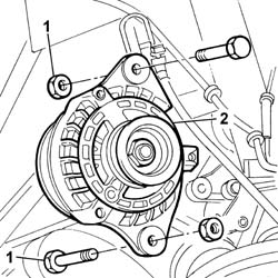
1. Undo the retaining bolts.
2. Remove the alternator rear mounting bracket.
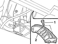
- Position the hydraulic engine support under the oil sump in order to work safely.
1. Remove the air intake chamber mounting bracket (1a) acting on the bolt (1b) and the nut (1c).
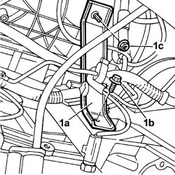
1. Disconnect the electrical connection for the engine oil pressure sensor.
| Description | Connector | |
|---|---|---|
| 1 | Insufficient engine oil pressure sensor | K030 |
2. Undo the nut fixing the support to the flexible mounting.
3. Undo the bolt fixing the support to the oil sump.
- Keep the spacers which are between the bolt and the sump.
4. Undo the bolts fixing the support to the cylinder block/crankcase.
5. Remove the intermediate driveshaft support which supports the engine.
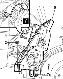
Refitting
- Still working with the hydraulic engine support positioned under the engine oil sump, fit the intermediate driveshaft support.
- Tighten the bolts fixing the support to the cylinder block/crankcase to the recommended torque.
| Value - daNm | Fastening | Component | Ø | |
|---|---|---|---|---|
| (to the cylinder block/crankcase) 5 | Bolt | RIGID REAR SUPPORT POWER UNIT | M12 X 1.25 |
- Position the spacers and tighten the bolt fixing the support to the oil sump to the recommended torque.
| Value - daNm | Fastening | Component | Ø | |
|---|---|---|---|---|
| (on the crankcase sump) 2.5 | Nut | RIGID REAR SUPPORT POWER UNIT | M8 |
- Tighten the nut fixing the support to the flexible mounting to the recommended torque.
| Value - daNm | Fastening | Component | Ø | |
|---|---|---|---|---|
| (to the flexible mounting) 5 | Nut | RIGID REAR SUPPORT POWER UNIT | M10 X 1.25 |
- Connect the electrical connection for the engine oil pressure sensor.
| Description | Connector | |
|---|---|---|
| Insufficient engine oil pressure sensor | K030 |
- Position the intake chamber mounting bracket.
- Fit the alternator rear mounting bracket.
- Remove the hydraulic support
- Position the alternator and fasten it using the fixing bolts.
| Value - daNm | Fastening | Component | Ø | |
|---|---|---|---|---|
| 5 | Nut | ALTERNATOR ASSEMBLY | M10 X 1.25 |
| Value - daNm | Fastening | Component | Ø | |
|---|---|---|---|---|
| 7 | Nut | ALTERNATOR ASSEMBLY | M12 X 1.25 |
- Connect the alternator electrical cables.
| Description | Connector | |
|---|---|---|
| Alternator | A010A |
| Description | Connector | |
|---|---|---|
| Alternator | A010B |
See in Op. 1092G10 Engine components single drive BELT - R.R.
See in Op. 1016A40 Ignition COIL COVER on cylinder head - R.R.
See in Op. 2710A30 INTERMEDIATE DRIVE SHAFT - R.R. with right driveshaft removed
See in Op. 7055B64 Engine compartment DUST SEAL in front wheel arch (one), left or right - R.R.
See in Op. 7055B42 FRONT WHEEL ARCH LINER (one), left or right - R.R.
See in Op. 4450B04 Right FRONT WHEEL (one) - R.R.
See in Op. 7055B54 PROTECTION/GUARD under engine - R.R.
See in Op. 7040D50 ENGINE COMPARTMENT UPPER SOUND INSULATION SHIELD - R.R.
- Connect the battery terminal.
- Remove the vehicle from the lift.
Removing
- Position the vehicle on a lift.
- Open the boot and disconnect the negative battery terminal.
See in Op. 7055B42 FRONT WHEEL ARCH LINER (one), left or right - R.R.
See in Op. 4450B04 Right FRONT WHEEL (one) - R.R.
See in Op. 7055B64 Engine compartment DUST SEAL in front wheel arch (one), left or right - R.R.
See in Op. 7055B54 PROTECTION/GUARD under engine - R.R.
See in Op. 7040D50 ENGINE COMPARTMENT UPPER SOUND INSULATION SHIELD - R.R.
See in Op. 1048A21 AIR INLET HOSE FROM INTAKE TO FILTER - R.R.
See in Op. 1048A28 vacuum air circuit resonator pipe - r+r
See in Op. 1008C10 Power unit REACTION ROD - Replace
See in Op. 1048A11 COMPLETE AIR FILTER -R.R.
See in Op. 1092G10 Engine components single drive BELT - R.R.
See in Op. 1072B50 Air CHAMBER - R.R.
See in Op. 2710A31 INTERMEDIATE DRIVE SHAFT - R.R.
See in Op. 1084B30 CARTRIDGE ENGINE OIL FILTER -R.R.
See in Op. 1076B84 EXHAUST PIPE BETWEEN RIGHT PRECONVERTER AND CATALYTIC CONVERTER - R.R.
See in Op. 1080B39 RIGHT CATALYTIC PRECONVERTER - R.R. or Replace Gasket
See in Op. 5530A10 ALTERNATOR - R.R.
See in Op. 1084C10 Engine oil heat exchanger - R.R.
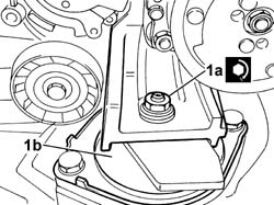
1. Undo the nut (1a) fixing the front engine support (1b) to the flexible mounting.
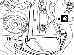
1. Position a hydraulic jack (1a) under the engine oil sump (1b).
2. Undo the nuts (2a) and the Allen screws (2b) fixing the rigid support (2c) to the cylinder block/crankcase.
3. Undo the centre nut (3a) fixing the support to the engine support frame (3b).
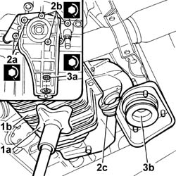
- Raise the jack, as necessary, and remove the support.
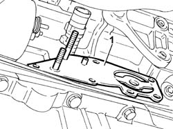
1. Remove the plate located between the support and the cylinder block/crankcase.
Refitting
- Still working with the hydraulic engine support positioned under the engine oil sump, fit the plate, then position the rigid rear support.
- Tighten the bolts and the nuts fixing the support to the cylinder block/crankcase to the recommended torque.
| Value - daNm | Fastening | Component | Ø | |
|---|---|---|---|---|
| (to the cylinder block/crankcase) 2 | Bolt | RIGID REAR SUPPORT POWER UNIT | M8 |
- Tighten the nut fixing the support to the flexible mounting to the recommended torque.
| Value - daNm | Fastening | Component | Ø | |
|---|---|---|---|---|
| (to the cylinder block/crankcase) 2 | Nut | RIGID REAR SUPPORT POWER UNIT | M8 |
- Tighten the nut fixing the support to the flexible mounting to the recommended torque.
| Value - daNm | Fastening | Component | Ø | |
|---|---|---|---|---|
| (to the flexible mounting) 4 | Nut | RIGID REAR SUPPORT POWER UNIT | M10 |
- Remove the hydraulic engine support
1. Tighten the nut (1a) fixing the front engine support to the flexible mounting (1b) to the recommended torque.
| Value - daNm | Fastening | Component | Ø | |
|---|---|---|---|---|
| 1a | 4,5 | Nut | FRONT FLEXIBLE MOUNTING BLOCKS, POWER UNIT | M10X1.25 |
See in Op. 1084C10 Engine oil heat exchanger - R.R.
See in Op. 5530A10 ALTERNATOR - R.R.
See in Op. 1080B39 RIGHT CATALYTIC PRECONVERTER - R.R. or Replace Gasket
See in Op. 1076B84 EXHAUST PIPE BETWEEN RIGHT PRECONVERTER AND CATALYTIC CONVERTER - R.R.
See in Op. 1084B30 CARTRIDGE ENGINE OIL FILTER -R.R.
See in Op. 2710A31 INTERMEDIATE DRIVE SHAFT - R.R.
See in Op. 1072B50 Air CHAMBER - R.R.
See in Op. 1092G10 Engine components single drive BELT - R.R.
See in Op. 1048A11 COMPLETE AIR FILTER -R.R.
See in Op. 1008C10 Power unit REACTION ROD - Replace
See in Op. 1048A28 vacuum air circuit resonator pipe - r+r
See in Op. 1048A21 AIR INLET HOSE FROM INTAKE TO FILTER - R.R.
See in Op. 7040D50 ENGINE COMPARTMENT UPPER SOUND INSULATION SHIELD - R.R.
See in Op. 7055B54 PROTECTION/GUARD under engine - R.R.
See in Op. 7055B64 Engine compartment DUST SEAL in front wheel arch (one), left or right - R.R.
See in Op. 4450B04 Right FRONT WHEEL (one) - R.R.
See in Op. 7055B42 FRONT WHEEL ARCH LINER (one), left or right - R.R.
- [0010T11]
- Connect the negative battery lead, then close the boot.
- Remove the vehicle from the lift.
Removing
- Position the vehicle on a lift.
- Open the boot and disconnect the negative battery terminal.
See in Op. 7040D50 ENGINE COMPARTMENT UPPER SOUND INSULATION SHIELD - R.R.
See in Op. 7055B54 PROTECTION/GUARD under engine - R.R.
See in Op. 4450B04 Right FRONT WHEEL (one) - R.R.
See in Op. 7055B42 FRONT WHEEL ARCH LINER (one), left or right - R.R.
See in Op. 7055B64 Engine compartment DUST SEAL in front wheel arch (one), left or right - R.R.
See in Op. 2710A30 INTERMEDIATE DRIVE SHAFT - R.R. with right driveshaft removed
See in Op. 1016A40 Ignition COIL COVER on cylinder head - R.R.
See in Op. 1092G10 Engine components single drive BELT - R.R.
1. Undo the bolts fixing the alternator.
- Disconnect the alternator electrical cables.
| Description | Connector | |
|---|---|---|
| Alternator | A010A |
| Description | Connector | |
|---|---|---|
| Alternator | A010B |
2. Remove the alternator.
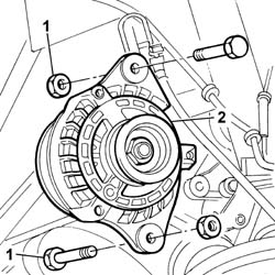
1. Undo the retaining bolts.
2. Remove the alternator rear mounting bracket.
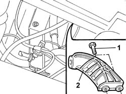
- Raise the lift.
1. Undo the fixing bolts (1a) and nuts (1b) and disconnect the earth lead (1c).
| Description | Connector | |
|---|---|---|
| 1c | Earth on engine | C040 |
- Lower the lift.
2. Release the wiring from the springs and remove the chamber mounting bracket.
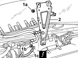
- Position the hydraulic engine support under the oil sump in order to work safely.
1. Disconnect the electrical connection for the engine oil pressure sensor.
| Description | Connector | |
|---|---|---|
| 1 | Insufficient engine oil pressure sensor | K030 |
2. Undo the nut fixing the support to the flexible mounting.
3. Undo the bolt fixing the support to the oil sump.
- Keep the spacers which are between the bolt and the sump.
4. Undo the bolts fixing the support to the cylinder block/crankcase.
5. Remove the intermediate driveshaft support which supports the engine.
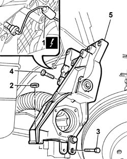
Refitting
- Still working with the hydraulic engine support positioned under the engine oil sump, fit the intermediate driveshaft support.
- Tighten the bolts fixing the support to the cylinder block/crankcase to the recommended torque.
| Value - daNm | Fastening | Component | Ø | |
|---|---|---|---|---|
| (to the cylinder block/crankcase) 5 | Bolt | RIGID REAR SUPPORT POWER UNIT | M12 X 1.25 |
- Position the spacers and tighten the bolt fixing the support to the oil sump to the recommended torque.
| Value - daNm | Fastening | Component | Ø | |
|---|---|---|---|---|
| (on the crankcase sump) 2.5 | Nut | RIGID REAR SUPPORT POWER UNIT | M8 |
- Tighten the nut fixing the support to the flexible mounting to the recommended torque.
| Value - daNm | Fastening | Component | Ø | |
|---|---|---|---|---|
| (to the flexible mounting) 5 | Nut | RIGID REAR SUPPORT POWER UNIT | M10 X 1.25 |
- Connect the electrical connection for the engine oil pressure sensor.
| Description | Connector | |
|---|---|---|
| Insufficient engine oil pressure sensor | K030 |
- Lower the lift.
- Positin the chamber mounting bracket on the vibration damper supports and secure it using the nuts.
- Raise the lift.
- Tighten the bolts fixing the bracket and fasten the earth lead.
| Description | Connector | |
|---|---|---|
| Earth on engine | C040 |
- Fit the alternator rear mounting bracket.
- Remove the hydraulic engine support.
- Position the alternator and fasten it using the fixing bolts.
| Value - daNm | Fastening | Component | Ø | |
|---|---|---|---|---|
| 5 | Nut | ALTERNATOR ASSEMBLY | M10 X 1.25 |
| Value - daNm | Fastening | Component | Ø | |
|---|---|---|---|---|
| 7 | Nut | ALTERNATOR ASSEMBLY | M12 X 1.25 |
- Connect the alternator electrical cables.
| Description | Connector | |
|---|---|---|
| Alternator | A010A |
| Description | Connector | |
|---|---|---|
| Alternator | A010B |
See in Op. 1092G10 Engine components single drive BELT - R.R.
See in Op. 1016A40 Ignition COIL COVER on cylinder head - R.R.
See in Op. 2710A30 INTERMEDIATE DRIVE SHAFT - R.R. with right driveshaft removed
See in Op. 7055B64 Engine compartment DUST SEAL in front wheel arch (one), left or right - R.R.
See in Op. 7055B42 FRONT WHEEL ARCH LINER (one), left or right - R.R.
See in Op. 4450B04 Right FRONT WHEEL (one) - R.R.
See in Op. 7055B54 PROTECTION/GUARD under engine - R.R.
See in Op. 7040D50 ENGINE COMPARTMENT UPPER SOUND INSULATION SHIELD - R.R.
- Connect the battery terminal.
- Remove the vehicle from the lift.
Removing
- Position the vehicle on a lift.
- Open the boot and disconnect the negative battery terminal.
See in Op. 7040D50 ENGINE COMPARTMENT UPPER SOUND INSULATION SHIELD - R.R.
See in Op. 7055B54 PROTECTION/GUARD under engine - R.R.
See in Op. 4450B04 Right FRONT WHEEL (one) - R.R.
See in Op. 7055B42 FRONT WHEEL ARCH LINER (one), left or right - R.R.
See in Op. 7055B42 FRONT WHEEL ARCH LINER (one), left or right - R.R.
See in Op. 7055B64 Engine compartment DUST SEAL in front wheel arch (one), left or right - R.R.
See in Op. 2710A31 INTERMEDIATE DRIVE SHAFT - R.R.
See in Op. 1092G10 Engine components single drive BELT - R.R.
1. Undo the bolts fixing the alternator.
2. Disconnect the alternator electrical wiring.
3. Remove the alternator.
| Description | Connector | |
|---|---|---|
| 2 | Alternator | A010A |
| Description | Connector | |
|---|---|---|
| 2 | Alternator | A010B |
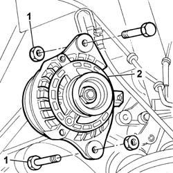
- Lower the lift.
1. Remove the alternator rear mounting bracket.
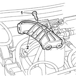
- Position the hydraulic engine support under the oil sump in order to work safely.
1. Disconnect the electrical connection for the engine oil pressure sensor.
| Description | Connector | |
|---|---|---|
| 1 | Insufficient engine oil pressure sensor | K030 |
2. Undo the nut fixing the support to the flexible mounting.
3. Undo the bolt fixing the support to the oil sump.
- Keep the spacers which are between the bolt and the sump.
4. Undo the bolts fixing the support to the cylinder block/crankcase.
5. Remove the intermediate driveshaft support which supports the engine.
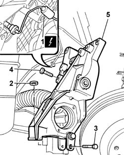
Refitting
- Position the engine support which also supports the intermediate driveshaft in the special housing.
- Tighten the bolts fixing the support to the engine support to the cylinder block/crankcase to torque.
| Value - daNm | Fastening | Component | Ø | |
|---|---|---|---|---|
| 5 | Bolt | RIGID REAR SUPPORT POWER UNIT | M10 X 1.25 |
- Tighten the bolt fixing the support to the oil sump to torque.
| Value - daNm | Fastening | Component | Ø | |
|---|---|---|---|---|
| 2.5 | Bolt | RIGID REAR SUPPORT POWER UNIT | M8 |
- Tighten the nut fixing the engine support to the flexible mounting on the chassis to torque.
| Value - daNm | Fastening | Component | Ø | |
|---|---|---|---|---|
| 5 | Nut | RIGID REAR SUPPORT POWER UNIT | M10 X 1.25 |
- Connect the electrical connection for the engine oil pressure sensor.
- Fit the alternator mounting bracket tightening the bolts fixing it to the cylinder block/crankcase to torque.
| Value - daNm | Fastening | Component | Ø | |
|---|---|---|---|---|
| 5 | Bolt | FRONT ALTERNATOR SUPPORT | M10 |
- Fit the alternator assembly and tighten the bolts fixing it to the mounting.
| Value - daNm | Fastening | Component | Ø | |
|---|---|---|---|---|
| 5 | Nut | ALTERNATOR ASSEMBLY | M10 X 1.25 |
| Value - daNm | Fastening | Component | Ø | |
|---|---|---|---|---|
| 7 | Nut | ALTERNATOR ASSEMBLY | M12 X 1.25 |
- Connect the alternator electrical wiring.
| Description | Connector | |
|---|---|---|
| Alternator | A010A |
| Description | Connector | |
|---|---|---|
| Alternator | A010B |
See in Op. 1092G10 Engine components single drive BELT - R.R.
See in Op. 2710A31 INTERMEDIATE DRIVE SHAFT - R.R.
See in Op. 7055B64 Engine compartment DUST SEAL in front wheel arch (one), left or right - R.R.
See in Op. 7055B42 FRONT WHEEL ARCH LINER (one), left or right - R.R.
See in Op. 4450B04 Right FRONT WHEEL (one) - R.R.
See in Op. 7055B54 PROTECTION/GUARD under engine - R.R.
- [7055B04]
See in Op. 7040D50 ENGINE COMPARTMENT UPPER SOUND INSULATION SHIELD - R.R.
- Connect the battery terminal.
Parts & tools for this job For 2002 Lancia Thesis
- PARTEngine gasket setSearch: Lancia Thesis 2002 engine gasket set
- TOOLTorque wrenchSearch: 3/8 inch torque wrench
- TOOLFeeler gauge setSearch: feeler gauge set
Links open Amazon search results in a new tab. As an Amazon Associate I earn from qualifying purchases.