
Pedal assembly - r r
- Make
- Lancia
- Model
- Ypsilon Factory Service Manual
- Year
- 2003–2011
- Section
- Hydraulic braking system › Pedal assembly - r r
Pedal assembly - r r
Removing
Ensure that the ignition key is in OFF position, then disconnect the battery negative terminal (-).
| Name | Connector | |
|---|---|---|
| Battery | A1B |
Proceed with removal - 1068A14 accelerator pedal - r + r.
Proceed with removal - 1068A20 accelerator pedal with built-in potentiometer - r r.
Proceed with removal - 7040A30 Left instrument panel lower TRIM - R.R..
Undo both bolts and remove the underfacia beam lower reinforcement.
For versions with VDC, before disconnecting the steering column universal joint, put on the steering lock to prevent rotation.
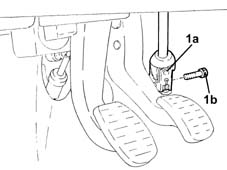
1. Release the steering column universal joint (1a) by undoing the bolt (1b) securing it to the steering box.
The bolt is pretreated and cannot therefore be refitted.
Proceed with removal - 1056B78 SWITCH on CLUTCH PEDAL - R.R..
Proceed with removal - 5550D10 brake light switch - r+r.
Proceed with removal - 1060G38 brake pedal switch - r r.
Proceed with removal - 1060G42 clutch pedal switch - r r.
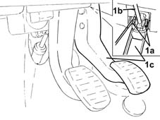
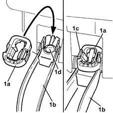
1. Working at the rear of the brake pedal, press the white coloured retaining tabs (1a) which secure the brake servo push rod (1b) to the brake pedal (1c).
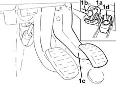
1. Remove the black coloured retaining device (1a), then release the brake servo push rod (1b) from the brake pedal (1c) and keep the cover (1d) for the brake servo push rod spherical head seat.
After each dismantling operation the black coloured retaining device (1a) for the brake servo push rod must always be replaced even if it appears to be intact.
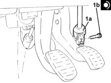
1. Release the retaining clips (1a) and disengage the clutch master cylinder push rod (1b) from the pedal.
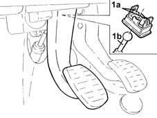
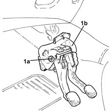
1. Undo the nuts (1a) and remove the pedal assembly (1b).
Refitting
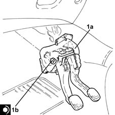
1. Fit the pedal assembly (1a) back in its housing and tighten the nuts (1b) to the specified torque.
| Fastening | Component | Ø | Value (daNm) | |
|---|---|---|---|---|
| Nut | PEDALS | M8 | (Brake servo/bodyshell side) 1.8 ÷ 2.6 |
Connect the clutch pedal by replacing in its seat and press the pedal fully down.
1. Fit the new retaining device (1a) onto brake pedal (1b) to secure the retaining clips (1c). Position the cover (1d) for the brake servo push rod spherical head.
After each dismantling operation the black coloured retaining device (1a) for the brake servo push rod must always be replaced even if it appears to be intact.
Lift up the brake pedal and position the brake servo push rod by the retaining device.
Press the brake pedal to engage the brake servo push rod with the retaining device.
Proceed with refitting - 1060G38 brake pedal switch - r r.
Proceed with refitting - 1060G42 clutch pedal switch - r r.
Proceed with refitting - 5550D10 brake light switch - r+r.
Proceed with refitting - 1056B78 SWITCH on CLUTCH PEDAL - R.R..
1. Connect the steering column universal joint (1a) and fasten it tightening the bolt (1b) to the recommended torque.
| Fastening | Component | Ø | Value (daNm) | |
|---|---|---|---|---|
| 1b | Bolt | INTERMEDIATE SHAFT CONNECTED TO STEERING BOX. | M10 | (Steering box side) 5.0 ÷ 6.1 |
Refit the underfacia beam lower reinforcement and tighten the bolts
Proceed with refitting - 7040A30 Left instrument panel lower TRIM - R.R..
Proceed with refitting - 1068A20 accelerator pedal with built-in potentiometer - r r.
Proceed with refitting - 1068A14 accelerator pedal - r + r.
Connect the negative (-) battery terminal.
Parts & tools for this job For 2003 Lancia Ypsilon
- PARTBrake padsSearch: Lancia Ypsilon 2003 brake pads
- TOOLBrake bleeder kitSearch: one man brake bleeder kit
- FLUIDBrake fluidSearch: brake fluid
Links open Amazon search results in a new tab. As an Amazon Associate I earn from qualifying purchases.