
CYLINDER HEAD GASKET (page 3 of 3)
- Make
- Land Rover
- Model
- Defender 300Tdi Defender
12
ENGINE
22
REPAIR
28. Lower cylinder head onto block ensuring correct
location with dowels.
NOTE: Cylinder head retaining bolts can
be used up to a maximum of five times.
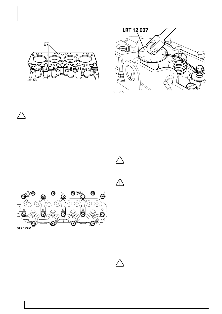
29. Lubricate threads of bolts with light oil and fit to
positions shown below. (Fit air cleaner mounting
bracket at positions 6 and 14).
Bolt sizes:
M10 x 117mm locations 3, 5, 12, and 13.
M12 x 140mm locations 1, 2, 7, 8, 9, 10, 15, 16, 17,
and 18.
M12 x 100mm locations 4, 6, 11, 14.
30. Tighten bolts so that underside of heads just
make contact with cylinder head.
31. Following the sequence indicated, tighten all
bolts to
40 Nm (30 lbf/ft).
32. Attach angle gauge LRT-12-007.
33. Make a suitable pointer from welding rod and
attach to a bolt screwed into a rocker shaft
securing bolt hole.
34. Tighten all bolts through 60
°
strictly in sequence
illustrated.
35. Repeat 60
°
tightening procedure, again strictly in
sequence illustrated.
36. Tighten the 10 longer bolts (M12 x 140mm) a
further 20
°
, again following the sequence
illustrated.
NOTE: Repositioning of the pointer will be
necessary to reach all bolts, the pointer
can be fitted to the rocker shaft securing
studs using 2 nuts.
CAUTION: The double tightening
procedure MUST be carried out, on no
account should the bolt tightening be
performed in one operation, otherwise damage to
the cylinder head may occur.
37. Fit valve stem caps.
38. Fit push rods to locations from which they were
removed.
39. Position rocker shaft assembly over locating
studs and fit retaining nuts and bolts, but do not
tighten at this stage.
40. Attach angle gauge LRT-12-007.
41. Make a suitable pointer and attach to one of the
rocker shaft locating studs.
42. Tighten all fixings in turn to
5 Nm (4 lbf/ft). Then
tighten a further 50
°
in same sequence.
NOTE: Repositioning of the pointer will be
necessary to reach all fixings.
Parts & tools for this job For Land Rover Defender
- PARTEngine gasket setSearch: Land Rover Defender engine gasket set
- TOOLTorque wrenchSearch: 3/8 inch torque wrench
- TOOLFeeler gauge setSearch: feeler gauge set
Links open Amazon search results in a new tab. As an Amazon Associate I earn from qualifying purchases.