
300Tdi Defender
REAR AXLE AND FINAL DRIVE
7
OVERHAUL
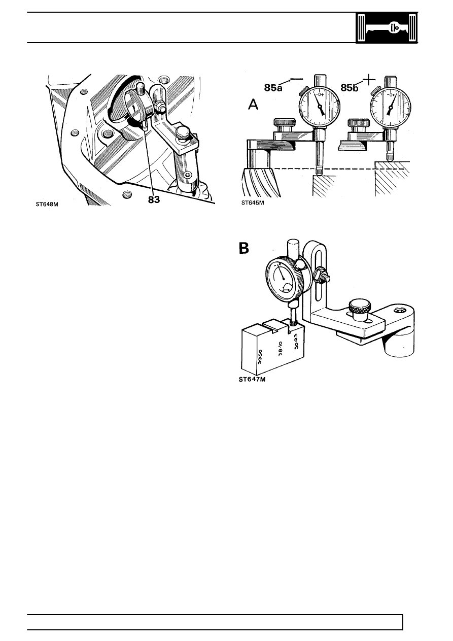
83. Position dial gauge centrally on pinion end face
with stylus registering on lowest point on one
differential bearing bore. Note dial gauge
deviation from zeroed setting.
84. Repeat on other bearing bore. Add together
readings, then halve sum to obtain mean
reading. Note whether stylus has moved up or
down from zeroed setting.
Example 1
Reading obtained LH side.............. + 0.1524mm
Reading obtained RH side............. - 0.0762mm
Add + 0.1524mm - 0.0762mm = + 0.0762mm
Divide by 2 (0.0762 divided by 2)= 0.0381mm
Therefore subtract 0.0381mm from shim thickness
behind pinion inner bearing track.
Example 2
Reading obtained LH side............. + 0.1524mm
Reading obtained RH side............ - 0.2032mm
Add + 0.1524mm - 0.2032mm = + 0.0508mm
Divide by 2 (0.0508 divided by 2)= 0.0254mm
Therefore add 0.0254mm from shim thickness behind
pinion inner bearing track.
85. Where stylus has moved down (85a), amount is
equivalent to thickness of shims that must be
removed from under pinion inner cup to bring
pinion down to nominal position. Where stylus
has moved up (85b), amount is equivalent to
additional thickness of shims required to bring
pinion up to nominal position.
Illustration A. Using setting gauge 18G191P.
Illustration B. Using universal setting block
LRT-54-503. This setting block has 3 setting heights.
Ensure that height marked 30.93 mm is used for this
differential.