
300Tdi Defender
51
REAR AXLE AND FINAL DRIVE
6
OVERHAUL
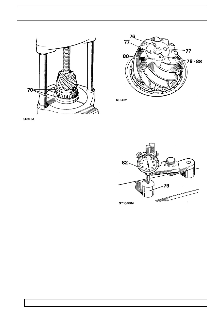
70. Press inner bearing cone onto drive pinion using,
LRT-51-502 details 1 and 2 and press
LRT-99-002.
71. Position pinion and bearing in casing; omit
collapsable spacer at this stage.
72. Fit outer bearing cone onto pinion.
73. Fit coupling flange and plain washer and loosely
fit flange nut.
74. Tighten coupling flange locknut to remove
end-float from pinion.
75. Rotate pinion to settle bearings and slowly
tighten flange locknut. Use a spring balance to
obtain a torque resistance of 11 Kgf/cm (18
lbf/in) to rotate pinion.
Drive pinion markings
76. Check that serial number marked on pinion end
face matches that marked on crown wheel.
77. The markings on end face adjacent to serial
number are of no significance during servicing.
78. The figure marked on end face opposite to serial
number indicates, in thousandths of an inch,
deviation from nominal required to correctly set
pinion. A pinion marked plus (+) must be set
below nominal, a minus (-) pinion must be set
above nominal. An unmarked pinion must be set
at nominal.
79. The nominal setting dimension is represented by
setting gauge block 18G191P or LRT-54-503,
which is referenced from pinion end face to
bottom radius of differential bearing bore. The
latter gauge is illustrated following instruction 85.
Drive pinion adjustment
80. Ensure that pinion end face is free of raised
burrs around etched markings.
81. Remove keep disc from magnetized base of dial
gauge tool 18G191.
82. Place dial gauge and setting gauge 18G191P or
LRT-54-503 on a flat surface and zero dial
gauge stylus on to setting gauge.