
TD5 Defender
12
ENGINE
32
OVERHAUL
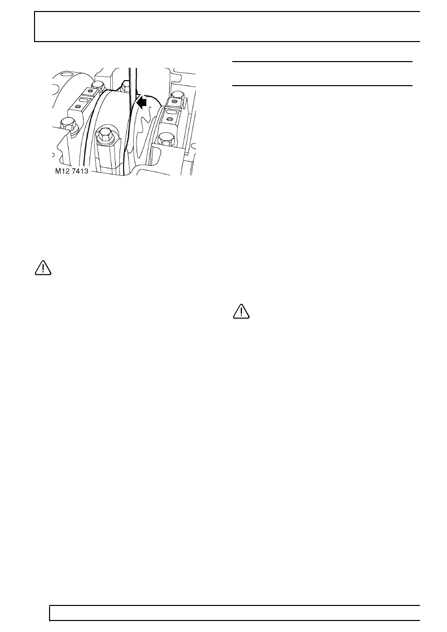
8. Carefully move connecting rod to one side of
journal and using feeler gauges, measure
end-float of connecting rod on journal:
Connecting rod end-float = 0.2 to 0.5 mm
(0.008 to 0.021 in).
CAUTION: If end-float exceeds limits
given, replace connecting rod and repeat
end-float check - See pistons, connecting
rods and cylinder bores.
9. Repeat above procedures for remaining big-end
bearings.
10. Fit oil pump. See this Section.
PISTONS, CONNECTING RODS AND CYLINDER
BORES
Service repair no - 12.17.02.01
Remove
1. Remove cylinder head gasket. See this
Section.
2. Remove connecting rod bearings. See this
Section.
3. Remove ridge of carbon from top of cylinder
bore.
4. Suitably identify each piston and connecting rod
assembly to its respective cylinder bore.
5. Carefully push connecting rod to top of cylinder
bore taking care that connecting rod does not
contact oil squirt jet or cylinder wall, remove
each piston and connecting rod assembly in
turn.
6. Using a suitable expander, remove and discard
piston rings from pistons.
7. Using a squared off end of an old piston ring,
clean carbon from ring grooves.
8. Clean carbon from piston crown and skirt.
CAUTION: Do not use abrasives on
graphited area of piston skirt, do not use a
wire brush or scraper on any part of the
pistons.
9. Secure connecting rod in a soft jawed vice.
10. Suitably identify each piston to its connecting rod
and fitted position of piston on rod.
11. Using suitable circlip pliers, remove and discard
2 circlips securing gudgeon pin.
12. Push gudgeon pin out of piston and connecting
rod; remove piston.
13. Suitably identify each gudgeon pin to its
respective piston.
14. Repeat above procedures for each piston.