
TD5 Defender
12
ENGINE
34
OVERHAUL
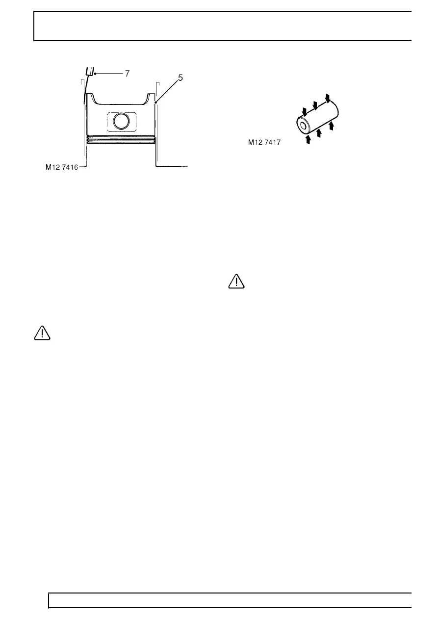
5. Starting with No. 1 piston, invert piston and with
arrow on piston crown pointing towards REAR of
cylinder block, insert piston into No. 1 cylinder
bore.
6. Position piston with bottom of skirt 25 mm (1.0
in) from top of cylinder bore.
7. Using feeler gauges, measure and record
clearance between piston skirt and LEFT HAND
side of cylinder bore 60 mm (2.4 in) from top of
bore:
Piston to cylinder bore clearance = 0.171 to
0.207 mm (0.007 to 0.008 in)
8. Repeat above procedures for remaining pistons.
CAUTION: Oversize pistons are not
available, if piston to cylinder bore
clearance exceeds limits given, repeat
check using a new piston; if clearances are still
excessive, replace cylinder block.
Piston and 1st compression rings fitted to Engine
Serial No. Prefixes 15P to 19P may be fitted to
Engine Serial No. Prefixes 10P to 14P in engine
sets only. Oil control and 2nd compression rings
are interchangeable between all engines.
9. Check fit of each gudgeon pin in its piston. Pin
must be a tight, sliding fit with no perceptible
side play.
10. Measure gudgeon pin diameter at each end and
centre of pin. Renew gudgeon pin and piston as
an assembly if diameters are less than specified
or if excessive pin to piston side play is evident.
Gudgeon pin diameter = 29.995 to 30.000 mm
(1.180 to 1.181 in)
11. Check connecting rod small-end bushes for
wear, check that gudgeon pin is a sliding fit in
the bush with no perceptible side play.
CAUTION: Small-end bushes cannot be
replaced, a new connecting rod must be
fitted.